Tag Archives: DWDM

What Is DWDM?

The Internet demand is always growing, especially the hugely popular video streaming services are increasing greatly. This provides a threat for the service provider. As the hottest topic in the telecommunication industry, DWDM offers unprecedented bandwidth which promises an effective solution to the challenges posted by the Internet growth. But what is DWDM, do you really know?

What Is DWDM?

DWDM wiki has defined it as an optical multiplexing technology. As one wavelength pattern of WDM system (the other pattern is CWDM), it stands for Dense Wavelength Division Multiplexing, which is used to increase bandwidth over existing fibre networks. This powerful technology can create multiple virtual optical fibres, so as to increase bandwidth on existing fibre optic backbones. It means that the fibre in DWDM system can transmit multiple signals of different wavelengths simultaneously. More specifically, the incoming signals are assigned to specific wavelengths within a designated frequency band, then the signals are multiplexed to one fibre. In addition, the most commonly used grid is the 100GHz grid, which consists of a spacing of 0.8nm per channel.

After knowing what is DWDM, we need to learn DWDM architecture. A typical DWDM architecture includes transmitter, receiver, optical amplifier, transponder, DWDM multiplexer and demultiplexer. Transmitter and receiver are the place where the source signal comes in and then multiplexed. Optical amplifier can amplify the signals in the wavelength range, which is very important for DWDM application. Transponder is the converter of wavelength. It’s responsible for converting the client optical signal back to an electrical signal. Multiplexer first combine multiple wavelengths of different fibre to one fibre, and at the receiving end, the demultiplexer separates all wavelengths of the composite signal onto individual fibres. Commonly, channels of DWDM Mux/Demux are available in 8, 16, 40 and 96 channels. All the DWDM basics work together to enable high capacity data flow in ultra-long distance transmission. The following figure is DWDM working principle.

what is DWDM

Why Use DWDM Technology?

The most obvious advantage of DWDM technology is providing the infinite transmission capacity, which would meet the increasing Internet demand. And more capacity can be added just by upgrading several equipment or increasing the number of lambdas on the optical fibre. Thus, the investment of DWDM technology has been reduced. Besides, DWDM technology also enjoys several other advantages, like the transparency and scalability.

Transparency. Due to DWDM is a physical layer architecture, it can support Time Division Multiplex and data formats like Gigabit Ethernet, Fibre Channel with open interfaces over a physical layer.

Scalability. It’s easy to be expanded. A single fibre can be divided into many channels, thus there is no need to add extra fibre but the wavelength will be increased. All these advantages make DWDM popular in the network.

Application of DWDM

As a new technology more applications of DWDM are yet to be tapped and explored. It was first deployed on long-haul routes. And now, DWDM technology is ready for long distance telecommunication operators. Using point to point or ring topology, the capacity will be dramatically improved without deploying an extra fibre. In the future, DWDM will continue to provide a higher bandwidth for the mass of data. With the development of technology, the system capacity will grow.

Conclusion

As for the question what is DWDM, I believe you have a good understanding of it. This powerful technology is related closely with current industry advancements trend. Now, service providers are faced with the sharp growth in demand for network capacity, DWDM is the best solution. With DWDM technology, the transmission work is no longer limited by the speed of available equipment, because it provides the high bandwidth without limit. We believe, DWDM will shine in the network world.

Economically Increase Network Capacity With CWDM Mux/DeMux

As the demands for voice, video and data networks are increasing dramatically, more bandwidth and higher transmission speed over long distances are needed. To meet these demands, it means that service providers should depend on more fibre optics which definitely cause more costs for optical devices. But they apply Wavelength Division Multiplexing (WDM) technologies which is a cost-effective way to increase capacity on the existing fibre infrastructure.

CWDM Technology

WDM technology multiplexes multiple optical signals onto a single fibre by using different wavelengths, or colors, of light. WDM can expand the network capacity using existing fibre infrastructure in an economical way. It includes CWDM (Coarse Wavelength Division Multiplexing) and DWDM (Dense Wavelength Division Multiplexing).

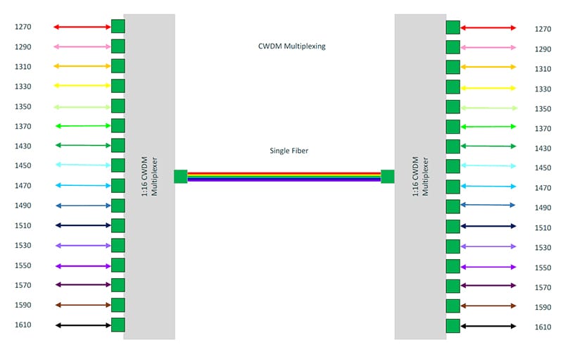
CWDM is a technology multiplexing 16 channels onto one single fibre between the wavelengths from 1270 nm to 1610 nm. It’s designed for city and access network. Since the channel spacing is 20 nm, CWDM is a more cost-effective method to maximize existing fibre by decreasing the channel spacing between wavelengths. CWDM is a passive technology, therefore, CWDM equipment needs no electrical power.

cwdm-channel

Figure 1

CWDM technology has been applied into wide areas, such as CWDM optical transceivers, CWDM OADM and CWDM Mux/DeMux. CWDM Mux/DeMux modules are multiplexers and demultiplexers which provide long distance coverage with premium optical technology to enhance fibre optic systems. It multiplexes signals of different wavelengths on one single fibre and demultiplexes wavelengths to individual fibres. CWDM Mux/DeMux can offer low-cost bandwidth and upgrade the existing system without leading spare costs on more fibres. CWDM Mux/DeMux can hold up to 18 channels of different standards (for example, Fibre Channel, Gigabit Ethernet) and data rates over one fibre optic link without interruption. FS.COM offers a full series of CWDM Mux/DeMux, including 2, 4, 8, 9, 12, 16, 18 channels with or without monitor port and expansion port in 1RU 19” rack chassis or pigtailed ABS module. The following will show you how to use a 18-channel CWDM Mux/DeMux to increase the data rates up to 180 Gbps on a fibre pair.

In Figure2, all Cisco compatible 10G CWDM SFP+ 1270-1610 nm 40km DOM transceivers on the switch are connected with the CWDM Mux/DeMux by LC-LC fibre patch cords. This CWDM Mux/DeMux has 18 channels and is designed as 1 RU rack mount size, covering the wavelengths from 1270 nm to 1610 nm and supporting LC UPC port. During the long distance transmission, only one single-mode armored LC fibre patch cord is needed to achieve 180 Gbps by connecting the two 18-channel CWDM Mux/DeMux. Thus, it greatly saves the cost for increasing the bandwidth on the existing fibre infrastructure.

cwdm-mux-18ch

Figure 2

FMU CWDM Mux/Demux

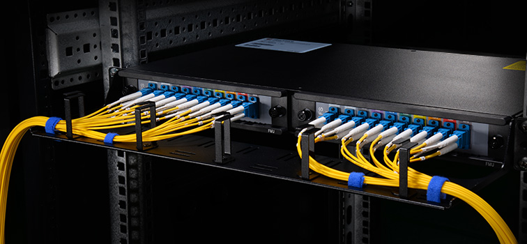
To increase the capacity, it requires more space and cable management is also a big trouble. So FS independently researched and developed FMU CWDM Mux/DeMux to solve this problem. We provide FMU 16-ch 1U Rack CWDM MUX/DEMUX specially designed as 2-slot plug and play style, which allows you to add or remove fibre optic cables and plug-in-modules freely according to your applications. There are two separate CWDM plug-in modules. One is high band (1470nm-1610nm) module with an expansion port and the other is low band (1270nm-1450nm, skip 1390nm, 1410nm) module without expansion port. Via this expansion port, channels can be expanded over one pair of fibre without interruption. You can also insert two CWDM Mux/DeMux FMU-plug-in modules without expansion port for two separated 8-channel connections. Besides, you can mix CWDM and DWDM system by adding CWDM Mux/DeMux FMU-plug-in modules and DWDM Mux/DeMux FMU-plug-in modules with matching wavelengths.

2-slot-cwdm-mux2

Figure 3

FS.COM FMU Plug-in Modules

The table below lists both single fibre and dual fibre FMU plu-in modules for 2-slot CWDM Mux/DeMux. You can choose suitable modules according to you specific requirements. Custom service is available, too.

ID# Description
58215 4 Channels 1270-1610nm Single Fibre CWDM Mux Demux, FMU Plug-in Module, LC/UPC
68215 9 Channels 1270-1610nm Single Fibre CWDM Mux Demux, FMU Plug-in Module, LC/UPC
42972 4 Channels 1270-1330nm Dual Fibre CWDM Mux Demux, FMU Plug-in Module, LC/UPC
43097 8 Channels 1470-1610nm Dual FibreCWDM Mux Demux, FMU Plug-in Module, LC/UPC
43099 8 Channels 1470-1610nm Dual FibreCWDM Mux Demux with Expansion Port, FMU Plug-in Module, LC/UPC
Conclusion

If you would like to increase your network bandwidth while spend less money on changing existing infrastructure, CWDM Mux/DeMux is an economical solution. FS.COM brings you high quality CWDM Mux/DeMux module and newly self-developed FMU 2-slot CWDM Mux/DeMux modules & FMU plug-in modules. For detailed information, please visit our site www.fs.com or contact us through sales@fs.com.

DWDM Techonology in Long-haul Optical Networks

In twenty-first century, there is a growing volume of data traffic which requires a higher bandwidth capacity. But this explosion in consumer demand for bandwidth makes long-haul networks cop with fibre exhaust. To respond to this explosive growth in bandwidth demand, many long-haul providers use dense wavelength division multiplexing (DWDM) technology to enhance the capacity of propagating data.

DWDM wavelength

Wave Division Multiplexing: Light in different colors can be combined on the same fibre

DWDM Solution — Efficient for Long-haul Provider

DWDM is an efficient solution for long-haul providers. It can increase the capacity of embedded fibre by first assigning incoming optical signals to specific frequencies within a designated frequency band and then multiplexing the resulting signals out onto one fibre. Compared to CWDM (coarse wavelength division multiplexing), DWDM has smaller channels spacing, enabling more signals with higher precision to be combined on the same fibre. It is typically used for long-haul system for its more channels to transport data. DWDM typically has the capability to transport up to 96 channels (wavelengths) in what is known as the Conventional band or C-band spectrum. Fiberstore provide DWDM Mux/Demux various from 4 channels to 96 channels. For better use at present and in the future, we offer plug-in FMU DWDM Mux/Demux (Check FMU DWDM Mux/Demux). With the advancement of DWDM technology, even 160 channels (wavelengths) can be transported within the same fibre, which allows as many as signals be transported simultaneously. DWDM can also combine multiple optical signals, which makes them be amplified as a group and transported in high speed and large volume. So DWDM technology is one of the best choices for transporting extremely large amounts of data traffic over metro or long distances in optical networks.

dwdm wavelength region

Wavelength Regions

DWDM Solution — Economical for Long-haul Provider

DWDM technology is also an economical solution for long-haul providers. A DWDM infrastructure can increase the distance between network elements, benefiting long-haul providers who look to reduce their initial network investments significantly. The fibre optic amplifier component of the DWDM system also enables long-haul providers to save costs without by taking in and amplifying optical signals without converting them to electrical signals. Furthermore, DWDM can provide a broad range of wavelengths in 1.55-μm region within C-band, which is showed in the picture “Wavelength Regions”. With a DWDM system multiplexing more wavelengths on a singer fibre, carriers can decrease the number of regenerators in a long-distance networks, resulting in fewer interruption and improved capacity with less loss.

Proven to be the optimal way of combining advanced functionality with cost efficient transport, DWDM technology is also friendly-used. The long-haul providers can integrate the DWDM technology easily with existing equipment in the network for the interface is bit-rate and format independent. And as continuous growth in data traffic, the long-haul providers will have an increasing reliance on improved DWDM technology to ensure good capacity of data transmission.

FS.COM DWDM Solution

Fiberstore supplies a complete series of WDM optical network solutions such as multiplexers, amplifiers, transceivers, etc. Especially, Fiberstore produce and stock for a full range of DWDM products to help build and expand fibre optic networks. For example, Fiberstore offers DWDM MUX/DEMUX Modules with 50GHz/100GHz/200GHz channel spacing, DWDM OADM modules with various configurations and DWDM Transceivers (SFP, SFP+, XFP, GBIC, X2, XENPAK) supporting 155Mbps to 10Gbps data transmissions.

Optical Multiplexing for High Speed Communication Systems

Introduction

Optical transmission uses pulses of light to transmit information from one place to another through an optical fibre. The light is converted to electromagnetic carrier wave, which is modulated to carry information as the light propagates from one end to another. The development of optical fibre has revolutionized the telecommunications industry. Optical fibre has replaced other transmission media such as copper wire since inception, and is mainly used to wire core networks. Today, optical fibre has been used to develop new high speed communication systems that transmit information as light pulses, examples are multiplexers/demultiplexers using the optical multiplexing technology.

What is Multiplexing?

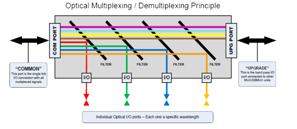
Multiplexer (Mux) is hardware component that combines multiple analog or digital input signals into a single line of transmission. And at the receiver’s end, the multiplexer is known as DeMultiplexer (DeMux)—performing reverse function of multiplexers. Multiplexing is therefore the process of combining two or more input signals into a single transmission. At receiver’s end, the combined signals are separated into distinct separate signal. Multiplexing enhances efficiency use of bandwidth. Here is a figure which shows the principle of optical multiplexing/demultiplexing.

Principle of Optical Multiplexing and DeMultiplexing

Optical Mux and DeMux are required to multiplex and demultiplex various wavelengths onto a single fibre link. Each specific I/O will be used for a single wavelength. One optical filter system can act as both Mux and DeMux. Optical Mux and DeMux are basically passive optical filter systems, which are arranged to process specific wavelengths in and out of the transport system (usually optical fibre). Process of filtering the wavelengths can be performed using Prisms, Thin Film Filter (TFF), and Dichroic filters or interference filters. The filtering materials are used to selectively reflect a single wavelength of light but pass all others transparently. Each filter is tuned for a specific wavelength.

Components of Optical Multiplexer

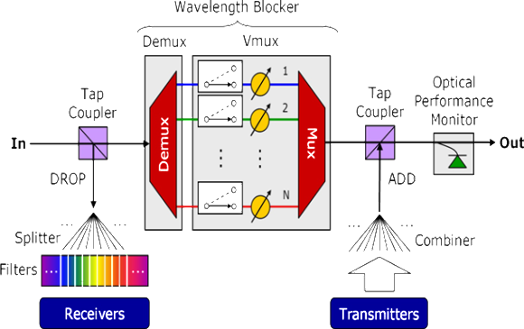
Generally, an optical multiplexer consists of Combiner, Tap Couplers (Add/Drop), Filters (Prisms, Thin film, or Dichroic), Splitter, and Optical Fibre. Here is a figure that shows the structure of a common optical multiplexer.

Structure of Optical Multiplexer

Optical Multiplexing Techniques

There are mainly three different techniques in multiplexing light signals onto a single optical fibre link: Optical Time Division Multiplexing (OTDM), Wavelength Division Multiplexing (WDM), and Code Division Multiplexing (CDM).

  1. OTDM: Separating wavelengths in time.
  2. WDM: Each channel is assigned a unique carrier frequency; Channel spacing of about 50GHz; Includes Coarse WDM (CWDM) and Dense WDM (DWDM).
    • CWDM: Characterized by wider channel spacing than DWDM.
    • DWDM: Uses a much narrower channel spacing, therefore, many more wavelengths are supported.
  3. CDM: Also used in microwave transmission; Spectrum of each wavelength is assigned a unique spreading code; Channels overlap both in time and frequency domains but the code guide each wavelength.

Applications

  • The major scarce resource in telecommunication is bandwidth—users want transmit at more high rate and service providers want to offer more services, hence, the need for a faster and more reliable high speed system.
  • Reducing cost of hardware, one multiplexing system can be used to combine and transmit multiple signals from Location A to Location B.
  • Each wavelength, λ, can carry multiple signals.
  • Mux/DeMux serve optical switching of signals in telecommunication and other field of signal processing and transmission.
  • Future next generation internet.

Advantages

  • High data rate and throughput: Data rates possible in optical transmission are usually in Gbps on each wavelength; Combination of different wavelengths means more throughput in one single communication systems.
  • Low attenuation: Optical communication has low attenuation compare to other transport system.
  • Less propagation delay.
  • More services offered.
  • Increase Return On Investment (ROI)
  • Low Bit Error Rate (BER)

Shortcomings

  • Fibre Output Loss and Dispersion: Signal is attenuated by fibre loss and distorted by fibre dispersion, then regenerator are needed to recover the clean purposes.
  • Inability of current Customer Premises Equipment (CPE) to receive at the same transmission rate of optical transmitting systems (achieving all-optical networks).
  • Optical-to-Electrical Conversion Overhead: Optical signals are converted into electrical signal using photo-detectors, switched and converted back to optical. Optical/electrical/optical conversions introduce unnecessary time delays and power loss. End-to-end optical transmission will be better.

Future Work

  • Research in optical end user equipment: Mobile phones, PC, and other handheld devices receiving and transmitting at optical rate.
  • Fast regeneration of attenuated signal.
  • Less distortion resulting from fibre dispersion.
  • End-to-end optical components: Eliminating the need for Optical-to-Electrical converter and vise versa.

Conclusion

While optical transmission is better compare to other transmission media because of its low attenuation and long distance transmission profile, optical multiplexing is useful in signal processing and transmission by transporting multiple signals using one single fibre link. As the growth of the internet requires fibre optic transmission to achieve greater throughput, optical multiplexing is also useful in image processing and scanning application.

Article Source: http://www.fiberopticshare.com/optical-multiplexing-for-high-speed-communication-systems.html

DWDM play an important role in submarine systems

Advantages of DWDM Multiplexer

DWDM is a very effective means of sharing transmission costs when fibre and other common components, such as optical amplifiers, dominate the overall system cost. The aggregate capacity of a single optical fibre can be increased by either increasing the bit rate or by increasing the number of wavelength channels using DWDM. The former requires development of new high-speed electronics, while DWDM allows fibre and fibre amplfier costs to be shared among all channels, driving down the total system cost per channel. Since information must still be coded onto the wavelength channels, today’s long-haul systems combine time-division multiplexing(TDM) with DWDM, taking advantage of high speed TDM advances to further reduce the system cost per bit per channel.
Fiberstore DWDM TECHNOLOGY

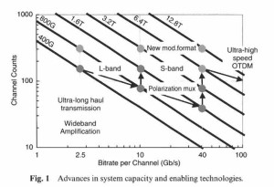
Both long-haul and undersea systems depend heavily on dense wavelength division multiplexed (DWDM) signals to achieve high-capacity transport.

Current long-haul system development efforts have focused on wide-band DWDM and ultra-long transport. These systems are enabled by new modulation formats, wideband amplification, wideband dispersion compensation and the use of forward error correction coding. Taken as a whole , these systems will deliver the lowest cost per transmitted bit over the longest distance . Optical fibre is an integral component of the entire system. T he fibre’s parametres have a significant impact on both cost and performance and influence the choice of most other components, such as amplifiers and compensators. In fact ,the use of wideband DWDM over ultra-long distances has elevated the fibre requirements in terms of dispersion management, nonlinear performance, distributed gain, spectral loss, and polarization mode dispersion (PMD).

History:

The first applications of fibre optic communication were to carry aggregated voice traffic between major metropolitan areas, such as the trunk lines from Washington, DC to Boston. In the United States, typical distances between major switch centres are on the order of 1600 km, while in Europe, these distances are typically 400 km. However, with the advent of all-optical or photonic switching located at these centres, the transmission distances without electronic regeneration could reach well into the thousands of kilometres in both cases, with the application space for these systems spilling over into the metro and regional networks. Such ultra-long distances have historically been reserved for point-to-point undersea fibre systems where transoceanic distances are typically 10,000 km and 4000 km for Trans-Pacific and Trans- Atlantic routes, respectively. As these distances are approached in terrestrial applications, it is not unreasonable to think of using similar system solutions for land applications.