Tag Archives: SFP

What is GBIC Module?

Nowadays, confusion appears when facing so many options on the fibre optic market, so being familiar with fibre optic equipment is helpful to select the one that exactly meets your need. When it comes to transceiver modules, various kinds of modules, like GBIC, SFP, QSFP, CFP and so on, may confuse you. What is GBIC? To help you get a general idea of GBIC module, this article will focus on what is GBIC module, types of GBIC and how to choose from GBIC and SFP.

What is GBIC?

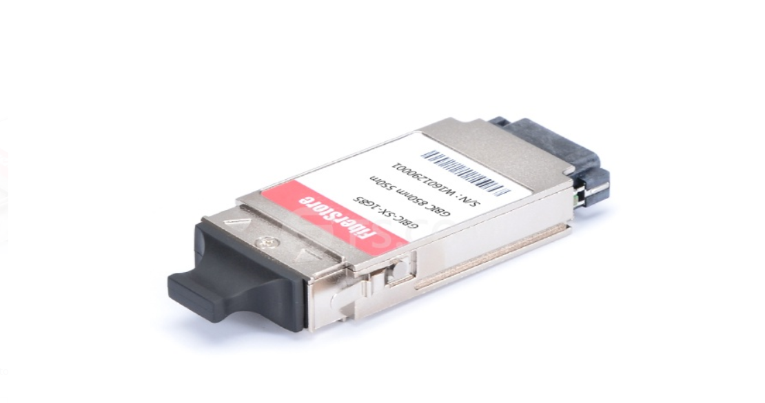
Short for gigabit interface converter, GBIC module is a transceiver which converts electric currents to optical signals and the other way around. It is hot pluggable and connects with fibre patch cable. With SC duplex interface, GBIC module works at the wavelength of 850nm to 1550nm and can transmit signals through the distance of 550m to 80km. It is a cost-effective choice for data centres and office buildings. As the improvement of fibre optic technology, mini GBIC came into being. It is regarded as the advanced GBIC, for it has half the size of GBIC, but supports the same data rate as GBIC. Mini GBIC is called small form factor pluggable (SFP) transceiver, which is a popular optical transceiver module on the market nowadays.

What is GBIC

Types of GBIC

There are many types of GBIC transceiver modules, which differs in transfer protocol, wavelength, cable type, TX power, transmission distance, optical components and receive sensitivity. The following chart will show you the details of them.

Type
1000BASE-SX GBIC
1000BASE-LX GBIC
1000BASE-EX GBIC
1000BASE-EX GBIC
1000BASE-ZX GBIC
Form Type
GBIC
GBIC
GBIC
GBIC
GBIC
Wavelength
850nm
1310nm
1310nm
1550nm
1550nm
Interface
SC duplex
SC duplex
SC duplex
SC duplex
SC duplex
Cable Type
MM
SMF
SMF
SMF
SMF
TX Power
-9.5~3dBm
-9~3dBm
-2~3dBm
-5~0dBm
-5~0dBm
Commercial Temperature Range
0 to 70°C (32 to 158°F)
Max Data Rate
1000Mbps
1000Mbps
1000Mbps
1000Mbps
1000Mbps
Max Cable Distance
550m
10km
40km
40km
80km
Optical Components
VCSEL 850nm
DFB 1310nm
DFB 1310nm
DFB 1550nm
DFB 1550nm
DOM Support
YES
YES
YES
YES
YES
Receiver Sensitivity
< -17dBm
< -21dBm
< -24dBm
< -24dBm
< -24dBm

GBIC vs SFP: Which to Choose?

As is shown in the above passage, GBIC and SFP are both used in 1Gbit data transmission. So which to choose? You know that SFP modules have a distinctly smaller size compared with GBIC transceiver modules. Obviously, SFP has the advantage of saving place, so there could be more interfaces to be used on a switch. When to choose which? It depends on the situation and your need. If you already have a line card, then you should choose GBIC or SFP modules according to your empty interfaces type. Besides, if you are planning to buy a new line card for your switch and want to make a decision of using GBIC or SFP modules, then how many interfaces you need to use is the important factor to consider. Generally speaking, SFP line card has a higher port density than GBIC line card for SFP has a smaller form factor than GBIC modules. So if you need 2 fibre interfaces on your switch, 2 port GBIC line card is a good choice. If you need to use over 24 interfaces on your switch, then 48 port SFP line card is more possible to meet your need.

Conclusion

What is GBIC? What are the types of GBIC? And how to choose from GBIC and SFP? This article has given you the answers. With the above information, it’s much more possible for you to choose a GBIC or SFP transceiver wisely. If you need a little more help and advice with any of GBIC or SFP optics, then please do not hesitate to let us know. FS.COM provides various kinds of fibre optic transceivers, including GBIC, 1G SFP, 10G SFP+, 40G QSFP, 100G QSFP28 and so on. For purchasing high-quality transceivers with low cost or for more products’ information, please contact us at sales@fs.com.

Quick Guides on 3G Digital Video SFPs

As high definition (HD) content occupies the norm in video and broadcasting industry, higher standards digital video SFPs are needed for HD or even higher standard video transmission. So there are 3G digital video SFPs suitable for SD/HD/3G-SDI. To know more about 3G digital video SFPs, please continue to read this article.

SDI Standards

SDI, short for Serial Digital Interface, is a digital video interface standard made by SMPTE (The Society of Motion Picture and Television Engineers) organization. The serial interface transmits the data through single channel. Additional SDI standards include HD-SDI, 3G-SDI, 6G-SDI, and 12G-SDI. HD-SDI was standardised by SMPTE 372M in 1998. It can support 1.485Gbps interface. 3G-SDI consists of a single 2.970Gbps serial link that allows replacing dual link HD-SDI.

3G Digital Video SFPs

3G Video SFP is also named Digital Video SFP. Digital video SFP modules are specially applied for SDI (Serial Digital Interface) data rates from 50 Mbps to 3 Gbps with links of 80 km over single-mode fibre. This kind of SFPs are designed to transmit optical serial digital signals as defined in SMPTE 297-2006, specifically for robust performance in the presence of SDI pathological patterns for SMPTE 259M, SMPTE 344M, SMPTE 292M and SMPTE 424M serial rates.

Digital video SFPs are hot pluggable, easy to use, and offer the highest density optical solution for carrying digital video through optical fibre. The digital video SFP pinout is designed as one slot can be populated with a dual transmitter, dual receiver, single transmitter, single receiver, or a transceiver. Digital video SFP is a cost-effective way to solve the problems during digital video optical transmission, allow the transport of SDI and HD-SDI video signals over any optical transport system that employs MSA standard optical transceivers.

3G digital video SFPs include 3G SDI SFP, BiDi SFP and CWDM SFP. According to different standards, it can be divided into different types. Based on the transmission mode, it can be divided into single Tx, single Rx, dual Tx, dual Rx and TR transceivers; by standards into MSA and non-MSA; by operating wavelength into 1310nm, 1490nm, 1550nm and CWDM wave length. 3G digital video SFPs also have 3G video SFP and 3G video pathological patterns due to different applications. Let’s take a look at the details about 3G video pathological patterns SFP.

What are 3G-SDI pathological patterns? Pathological patterns, also called SDI proving ground, are a whole test signal. And it must be done during blackout. This signal is tough to handle by serial digital system, and significant to check the system performance. Pathological patterns often contain the richest low-frequency energy which statistically happens one per frame. Pathological patterns test is also an important indicator of video SFP modules. FS.COM 3Gbps video pathological patterns SFPs are used to transmit optical serial digital signals at the serial rates of SMPTE 259M, SMPTE 344M, SMPTE 292M and SMPTE 424M defined in SMPTE 297-2006. 3Gbps video pathological patterns SFPs with LC interface can transmit optical signals from 50Mbps to 3Gbps reaching the maximum distance of 40km. Both single-mode and multimode video pathological patterns SFPs are available. All modules are hot-pluggable and compatible with SFP MSA. Besides, they can be applied in 3G-SDI/HD-SDI/SD-SDI electrical-optical converter, 3G-SDI/HD-SDI/SD-SDI optical-electrical converter, HD camera or monitor system and high-density digital video routers & switches.

3G-Digital-Video-SFPs-application

Conclusion

From this article, you must know some information about 3G digital video SFP. Fiberstore offers a full series of low cost but high quality 3G digital video SFPs for your applications covering the link distance of 300 m, 10 km, 20 km, 40 km and 80 km. As the advent of 4K (ultra high definition) market, the demand is growing fast for transporting the 4K in an efficient way. So just expect 6G-SDI or even 12G-SDI products researched and developed by FS.COM.

Things You Need to Know Before Deploying 10 Gigabit Ethernet Network

Since the establishment of 10 Gigabit Ethernet, it has been employed by large amount of enterprises in their corporate backbones, data centres, and server farms to support high-bandwidth applications. But how to achieve a reliable, stable and cost-effective 10Gbps network? There are ten things you should know before doing the deployment.

More Efficient for the Server Edge

Many organizations try to optimize their data centres by seeking server virtualization which supports several applications and operating systems on a single server by defining multiple virtual machines on the server. Because of this, the organizations can reduce server inventory, better utilize servers, and mange resources more efficiently. Server virtualization relies heavily on networking and storage. Virtual machines require lot of storage. The network connectivity between servers and storage must be fast enough to avoid bottlenecks. And 10GbE can provide the fast connectivity for virtualized environments.

More Cost-effective for SAN

There are three types of storage in a network: direct-attached storage, network attached storage, and SAN. Among them, SAN is the most flexible and scalable solution for data centre and high-density applications. But it costs much and needs special trainees for installing and maintaining the Fibre Channel interconnect fabric.

The internet small computer system interface (iSCSI) makes 10 Gigabit Ethernet an attractive interconnect fabric for SAN applications. iSCSI allows 10 Gigabit Ethernet infrastructure to be used as a SAN fabric which is more favorable compared with Fibre Channel. Because it can reduce equipment and management costs, enhance server management, improve disaster recovery and deliver excellent performance.

Reducing Bottlenecks for the Aggregation Layer

Today, traffic at the edge of the network has increased dramatically. Gigabit Ethernet to the desktop has become more popular since it becomes less expensive. More people adopt Gigabit Ethernet to the desktop, which increases the oversubscription ratios of the rest of the network. And that brings the bottleneck between large amounts of Gigabit traffic at the edge of the network and the aggregation layer or core.

10 Gigabit Ethernet allows the aggregation layer to scale to meet the increasing demands of users and applications. It can well solve the bottleneck for its three advantages. First, 10 Gigabit Ethernet link uses fewer fibre stands compared with Gigabit Ethernet aggregation. Second, 10 Gigabit Ethernet can support multi Gigabit streams. Third, 10 Gigabit Ethernet provides greater scalability, bringing a future-proof network.

Fibre Cabling Choices

To realize 10 Gigabit Ethernet network deployment, three important factors should be considered, including the type of fibre cable (MMF of MF), the type of 10 Gigabit Ethernet physical interface and optics module (XENPAK, X2, XFP and SFP+).

Cable Types Interface Max Distance
MMF (OM1/OM2/OM3) 10GBASE-SR 300 m
10GBASE-LRM 220 m
10GBASE-ER 40 km
SMF (9/125um fibre) 10GBASE-LR 10 km
10GBASE-ZR 80 km

Form factor options are interoperable when 10 Gigabit Ethernet physical interface type is the same on both ends of the fibre link. For example, 10GBASE-SR XFP on the left can be linked with one 10GBASE-SR SFP+ on the right. But 10GBASE-SR SFP+ can’t connect to one 10GBASE-LRM SFP+ at the other end of the link.

Copper Cabling Solutions

As copper cabling standards becomes mature, the copper cabling solutions for 10GbE is becoming common. Copper cabling is suitable for short distance connection. The are three different copper cabling solutions for 10 Gigabit Ethernet: 10GBASE-CX4, SFP+ DAC (direct attach cable) and 10GBASE-T.

10GBASE-CX4 is the first 10 Gigabit Ethernet standard. It’s economical and allowed for very low latency. But it’s a too large form factor for high density port counts in aggregation switches.

10G SFP+ DAC is a new copper solution for 10 Gigabit Ethernet. It has become the main choice for servers and storage devices in a rack because of its low latency, small connector and reasonable cost. It’s the best choice for short 10 Gigabit Ethernet network connection.

10GBASE-T runs 10G Ethernet over Cat6a and Cat7 up to 100 m. But this standard is not very popular since it needs technology improvements to reduce its cost, power consumption, and latency.

For Top of Rack Applications

A top-of-rack (ToR) switch is a switch with a low number of ports that sits at the very top or in the middle of a 19’’ telco rack in data centres. A ToR switch provides a simple, low-cost way to easily add more capacity to a network. It connects several servers and other network components such as storage together in a single rack.

ToR switch uses SFP+ to provide 10G network in an efficient 1U form factor. DAC makes rack cabling and termination easier. Each server and network storage device can be directly connected to the ToR switch, eliminating the need for intermediate patch panels. DAC is flexible for vertical cabling management within the rack architecture. And the cabling outside the rack, the ToR switch uplink connection to the aggregation layer, simplifies moving racks.

The following figure shows a 10 Gigabit Ethernet ToR switching solution for servers and network storage. Because the servers are virtualized, so the active-active server team can be distributed across two stacked witches. This can ensure physical redundancy for the servers while connected to the same logical switch. What’s more, failover protection can be offered if one physical link goes down.

10G-ToR

Conclusion

10 Gigabit Ethernet network is not the fastest but quite enough for common use in our daily life. So you should better read this article before you do the deployment. Besides, FS.COM provides both fibre and copper cabling solutions for 10G network. For more details, please visit www.fs.com.

Brief Analysis on Fibre Channel Technology

Fibre Channel is a set of advanced data transport standards that allow large amounts of data to be moved at multi-gigabit speeds between computers, servers, and other devices. Fibre Channel is widely applied because its high bandwidth, proven reliability and some other benefits. This article will talk about Fibre Channel information.

fiber-channel-network

“Fibre” and “Fiber”

You must be confused the name of this standard. Why is it called “Fibre Channel” instead of “Fiber Channel”? The words “Fiber” and “Fibre” have the same meaning (“Fiber” is the international English spelling style, while “Fibre” is British style). “Fibre Channel” is the official spelling for the technology. “Fiber” just means the transmission media used in optical connections. The term “Fibre” is used by the Fibre Channel standard to refer to all the supported physical media types.

Fibre Channel Development History

Fibre Channel started in the late 1980s as part of the IPI (intelligent peripheral interface) to increase the capabilities of the IPI protocol. Fibre Channel was approved in 1988. The development of Fibre Channel standards serves as a model for the creation of modern transfer technology. From the beginning to its approval, it has gone through a number of iterations. Since it became more interoperable with other protocols and devices, it finally got the approval of American National Standards Institute (ANSI) in 1994.

At first, Fibre Channel was used in banks, large companies, and data centres. The installation is too complex especially when the transmitting media is optical fibre. But that bad situation has been changed. Today Fibre Channel seems to be a good choice for organizations with growing data storage needs.

Fibre Channel Benefits

Fibre Channel is more likely to be a high-speed switching system that interconnects local devices. Fibre Channel has the benefits of high speed, easy scalability, and attainable network lengths.

    • High speed. Fibre Channel can provide consistent bandwidth of 2 Gbps or 4 Gbps. The rate is expected to double in a few years to 8 Gbps. It will meet the increasing needs of network users.
    • Scalability. Fibre Channel networks perform with equal reliability, high rates, and flexible configuration. So it’s scalable up to thousands of ports even though device connections consist hundreds of integrated servers from different vendors.
    • Guaranteed in-order delivery. Fibre Channel in-order delivery of raw block data. In-order delivery greatly boosts network efficiency. And some applications like video and IP streaming require this. Fibre Channel can naturally streams video frames in order, reducing bottlenecks that would degrade the video’s required speed per second.
Fibre Channel Deployment

A successful network deployment requires a lot. You must first know your needs and decide which type of Fibre Channel is the best suitable for your network. Is it a new network or an additional one? What’s the total physical length of the network? How many devices? To answer these questions, you may consider the cabling and connector type.

fc-deployment

Cable — Copper or Fibre

It’s important to choose the right cable type for your network interconnection. To choose copper or fibre, it depends on the distances between the Fibre Channel devices being about to be connected.

Copper cable can be used for short distance. It’s typical in point-to-point and other topologies when devices are mounted in the same rack or are located in the same room. Copper cable is durable and can withstand being stepped on or pulled. It’s easy for installation and maintenance.

While, fibre optic cable is for long distance since the distance between devices become longer than before, maybe in different buildings or on different floors of a building. Compared to copper cable, fibre optic cable is immune to the electrical resistance and electromagnetic interference (EMI) which affect signals carried over copper cable. It can support higher data rates. But the problem is that the signal strength over fibre cable is easily to be damaged by the dirt, dust or other material defects in the fibre cable. So fibre optic testing is a must for high performance of the entire network. And much more cares and special tools are needed during fibre optic cable installation.

Connector

Nearly all Fibre Channel switches requires SFP transceiver modules. It’s very common to see 2G and 4G Fibre Channel SFP transceivers in the fibre optics market. For 2G and 4G FC SFPs, the interface is designed as “LC duplex”. When plug in LC patch leads, you should better avoid touching the end face of the connector to ensure the network work with long-term, consistent performance and reliability. If the cable is not preterminated, it will be more complex. You need to strip cable’s outer jacket and the fibre coating to attach the connector. All fibre optic connectors should be carefully tested after installation. If it’s possible, try to buy high quality and certified preterminated cables from reliable vendors.

Conclusion

Fibre Channel is a flexible, scalable, high-speed data transfer interface that can operate over both copper and fibre optical cable. FS.COM provides 2G and 4G Fibre Channel SFP transceivers which can support distance up to 80 km. All the transceivers have been fully tested. We also offer preterminated duplex LC patch cords for Fibre Channel deployment. For more detailed information, please contact via sales@fs.com.


The Recognition of Fiber Optic Transceiver

Fiber Optic Transceiver Overview

What is an Optical Transceiver Module?
A fiber optical transceiver is a device that can send and receive optical information. By using an optical transceiver, network spend less space and steer clear of the necessity of getting a transmitter and receiver in the network. Able to transmit information further and faster than older models, the more recent transceivers are utilized and appearance, creating more compact, smaller sized modules than ever before.

How does it work?
A fiber optic transceiver is a accessory acclimated to forward and accept optical information. There are a number of different components on these devices, including a light source and an electrical component. The transceiver has two ends, one that an optical cable plugs into and accession for abutting an electrical device. Fiber optic transceivers combine a fiber optic transmitter and a fiber optic receiver in a single module. They are arranged in parallel so that they can operate independently of each other. Both the receiver and the transmitter have their own circuitry and can handle transmissions in both directions. In fiber optic data links, the transmitter converts an electrical signal into an optical signal, which is coupled with a connector and transmitted through a fiber optic cable. The light from the end of the cable is coupled to a receiver, where a detector converts the light back into an electrical signal. Either a light emitting diode (LED) or a laser diode is used as the light source.

Principle of Optical Transceiver Modules
Optical transceiver generally includes both a transmitter and a receiver in a single module. The transmitter and receiver are arranged in parallel so that they can operate independently of each other. Both the receiver and the transmitter have their own circuitry so that they can handle transmissions in both directions. The transmitter takes an electrical input and converts it to an optical output from a laser diode or LED. The light from the transmitter is coupled into the fiber with a connector and is transmitted through the fiber optic cable plant. The light from the end of the fiber is coupled to a receiver where a detector converts the light into an electrical signal which is then conditioned properly for use by the receiving equipment.

Optical Transceiver Solution

Application of Optical Transceiver Modules
Optical transceiver, essentially just completed the converted of data between different media, can realize the connection between two switches or computers in the 0-120km distance. Its main function is to achieve the conversion between optical-electrical and electrical-optical, including optical power control, modulation transmission, signal detection, IV conversion and limiting amplifier decision regeneration. In addition, there are some functions like security information query, TX-disable. Here is a summary in the practical application.

  1. Optical transceivers can interconnect with switches.
  2. Optical transceivers can interconnect between the switch and the computer.
  3. Optical transceivers can interconnect with computers.
  4. Optical transceivers can act as the transmission repeater.
    When the actual transfer distance exceeds the nominal transmission distance of the transceiver, in particular, the actual transfer distance exceeds 120km alerts, with 2 sets transceiver back to back in the case of on-site conditions allow, repeaters or the use of “optical-optical” conversiona relay, is a very cost-effective solution.
  5. Optical transceivers can offer conversion between single-mode and multimode fiber connection.
    When the networks appear to need a single multimode fiber connection, you can use a multimode transceiver and a single-mode transceiver back-to-back connections, which can solve the problem of single multimode fiber converted.
  6. Optical transceivers can offer WDM transmission.
    The lack of resources of long-distance fiber optic cable, in order to improve the utilization rate of the fiber optic cable, and reduce the cost, transceiver and wavelength division multiplexer (WDM multiplexer) with the use of two-way information on the same fiber transmission.

Optical Transceiver modules can be classified according to the following aspects.

1. Optical Fiber Type
Single-mode fiber transceiver and Multimode fiber transceiver. The single-mode version has a transmission distance of 20 to 120 km, while the multimode one’s is 2 to 5 km. Due to the different transmission distance, the transceivers’ transmit power, receiver sensitivity and the use of wavelength will be different.

2. Optical Fiber Count
Simplex fiber transceiver and Duplex fiber transceiver. The simplex version receives the data sent in a single fiber transmission, While the duplex one receives data transmitted on a dual fiber transmission.By definition, single fiber devices can save half of the fiber, a fiber that is in the receive and transmit data, where the fiber is very applicable to resource constraints. These products use the wavelength division multiplexing techniques, mostly using the wavelength 1310nm and 1550nm.

3. Transmission Rate
Transmission rate refers to the number of gigabits transmitted per second, per unit of Mbps or Gbps. Optical modules cover the following main rate: low rates, Fast, Gigabit, 1.25G, 2.5G, 4.25G, 4.9G, 6G, 8G, 10G and 40G.

4. Package
SFP, SFP+, GBIC, XFP, XENPAK, X2, 1X9, SFF, 200/3000pin, XPAK, etc.

Fiberstore Optical Transceiver Solution

Fiberstore is a worldwide leading manufacturer & supplier of compatible fiber optical transceivers. We produce and stock for a full range of transceivers such as SFP Plus (SFP+), X2, XENPAK, XFP, SFP, GBIC. In the market, there are many brands of fiber optic transceiver, such as HP, Cisco, NETGEAR, Dell, etc. The following table is the order information of HP SFP transceiver:

Part No. Description
SFP-1GT-1MA-HP HP JD089B X120 compatible 1000BASE-T SFP Copper RJ45 100m
SFP-1G85-5MA-HP HP JD118B X120 compatible 1000BASE-SX SFP 850nm 550m DDM MMF
SFP-1G31-10A-HP HP JD119B X120 compatible 1000BASE-LX SFP 1310nm 10km SMF
SFP-1G85-5ME-HP HP J4858B X121 compatible 1000BASE-SX SFP 850nm 550m MMF
SFP-1G85-5MF-HP HP J4858C X121 compatible 1000BASE-SX SFP 850nm 550m MMF
SFP-1GT-1MD-HP HP J8177C X121 compatible 1000BASE-T SFP Copper RJ45 100m
SFP-1G31-10F-HP HP J4859C X121 compatible 1000BASE-LX SFP 1310nm 10km SFP SMF
BLSFP-1G34-10-HP HP J9143B X122 compatible 1000BASE 1310nmTX/1490nmRX BIDI SFP 10km SMF