Tag Archives: WDM

What Is DWDM?

The Internet demand is always growing, especially the hugely popular video streaming services are increasing greatly. This provides a threat for the service provider. As the hottest topic in the telecommunication industry, DWDM offers unprecedented bandwidth which promises an effective solution to the challenges posted by the Internet growth. But what is DWDM, do you really know?

What Is DWDM?

DWDM wiki has defined it as an optical multiplexing technology. As one wavelength pattern of WDM system (the other pattern is CWDM), it stands for Dense Wavelength Division Multiplexing, which is used to increase bandwidth over existing fibre networks. This powerful technology can create multiple virtual optical fibres, so as to increase bandwidth on existing fibre optic backbones. It means that the fibre in DWDM system can transmit multiple signals of different wavelengths simultaneously. More specifically, the incoming signals are assigned to specific wavelengths within a designated frequency band, then the signals are multiplexed to one fibre. In addition, the most commonly used grid is the 100GHz grid, which consists of a spacing of 0.8nm per channel.

After knowing what is DWDM, we need to learn DWDM architecture. A typical DWDM architecture includes transmitter, receiver, optical amplifier, transponder, DWDM multiplexer and demultiplexer. Transmitter and receiver are the place where the source signal comes in and then multiplexed. Optical amplifier can amplify the signals in the wavelength range, which is very important for DWDM application. Transponder is the converter of wavelength. It’s responsible for converting the client optical signal back to an electrical signal. Multiplexer first combine multiple wavelengths of different fibre to one fibre, and at the receiving end, the demultiplexer separates all wavelengths of the composite signal onto individual fibres. Commonly, channels of DWDM Mux/Demux are available in 8, 16, 40 and 96 channels. All the DWDM basics work together to enable high capacity data flow in ultra-long distance transmission. The following figure is DWDM working principle.

what is DWDM

Why Use DWDM Technology?

The most obvious advantage of DWDM technology is providing the infinite transmission capacity, which would meet the increasing Internet demand. And more capacity can be added just by upgrading several equipment or increasing the number of lambdas on the optical fibre. Thus, the investment of DWDM technology has been reduced. Besides, DWDM technology also enjoys several other advantages, like the transparency and scalability.

Transparency. Due to DWDM is a physical layer architecture, it can support Time Division Multiplex and data formats like Gigabit Ethernet, Fibre Channel with open interfaces over a physical layer.

Scalability. It’s easy to be expanded. A single fibre can be divided into many channels, thus there is no need to add extra fibre but the wavelength will be increased. All these advantages make DWDM popular in the network.

Application of DWDM

As a new technology more applications of DWDM are yet to be tapped and explored. It was first deployed on long-haul routes. And now, DWDM technology is ready for long distance telecommunication operators. Using point to point or ring topology, the capacity will be dramatically improved without deploying an extra fibre. In the future, DWDM will continue to provide a higher bandwidth for the mass of data. With the development of technology, the system capacity will grow.

Conclusion

As for the question what is DWDM, I believe you have a good understanding of it. This powerful technology is related closely with current industry advancements trend. Now, service providers are faced with the sharp growth in demand for network capacity, DWDM is the best solution. With DWDM technology, the transmission work is no longer limited by the speed of available equipment, because it provides the high bandwidth without limit. We believe, DWDM will shine in the network world.

Economically Increase Network Capacity With CWDM Mux/DeMux

As the demands for voice, video and data networks are increasing dramatically, more bandwidth and higher transmission speed over long distances are needed. To meet these demands, it means that service providers should depend on more fibre optics which definitely cause more costs for optical devices. But they apply Wavelength Division Multiplexing (WDM) technologies which is a cost-effective way to increase capacity on the existing fibre infrastructure.

CWDM Technology

WDM technology multiplexes multiple optical signals onto a single fibre by using different wavelengths, or colors, of light. WDM can expand the network capacity using existing fibre infrastructure in an economical way. It includes CWDM (Coarse Wavelength Division Multiplexing) and DWDM (Dense Wavelength Division Multiplexing).

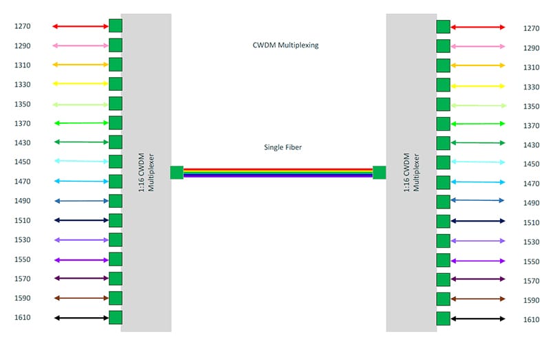
CWDM is a technology multiplexing 16 channels onto one single fibre between the wavelengths from 1270 nm to 1610 nm. It’s designed for city and access network. Since the channel spacing is 20 nm, CWDM is a more cost-effective method to maximize existing fibre by decreasing the channel spacing between wavelengths. CWDM is a passive technology, therefore, CWDM equipment needs no electrical power.

cwdm-channel

Figure 1

CWDM technology has been applied into wide areas, such as CWDM optical transceivers, CWDM OADM and CWDM Mux/DeMux. CWDM Mux/DeMux modules are multiplexers and demultiplexers which provide long distance coverage with premium optical technology to enhance fibre optic systems. It multiplexes signals of different wavelengths on one single fibre and demultiplexes wavelengths to individual fibres. CWDM Mux/DeMux can offer low-cost bandwidth and upgrade the existing system without leading spare costs on more fibres. CWDM Mux/DeMux can hold up to 18 channels of different standards (for example, Fibre Channel, Gigabit Ethernet) and data rates over one fibre optic link without interruption. FS.COM offers a full series of CWDM Mux/DeMux, including 2, 4, 8, 9, 12, 16, 18 channels with or without monitor port and expansion port in 1RU 19” rack chassis or pigtailed ABS module. The following will show you how to use a 18-channel CWDM Mux/DeMux to increase the data rates up to 180 Gbps on a fibre pair.

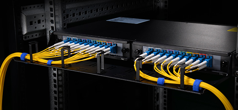
In Figure2, all Cisco compatible 10G CWDM SFP+ 1270-1610 nm 40km DOM transceivers on the switch are connected with the CWDM Mux/DeMux by LC-LC fibre patch cords. This CWDM Mux/DeMux has 18 channels and is designed as 1 RU rack mount size, covering the wavelengths from 1270 nm to 1610 nm and supporting LC UPC port. During the long distance transmission, only one single-mode armored LC fibre patch cord is needed to achieve 180 Gbps by connecting the two 18-channel CWDM Mux/DeMux. Thus, it greatly saves the cost for increasing the bandwidth on the existing fibre infrastructure.

cwdm-mux-18ch

Figure 2

FMU CWDM Mux/Demux

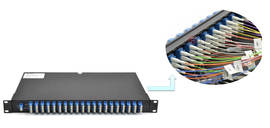
To increase the capacity, it requires more space and cable management is also a big trouble. So FS independently researched and developed FMU CWDM Mux/DeMux to solve this problem. We provide FMU 16-ch 1U Rack CWDM MUX/DEMUX specially designed as 2-slot plug and play style, which allows you to add or remove fibre optic cables and plug-in-modules freely according to your applications. There are two separate CWDM plug-in modules. One is high band (1470nm-1610nm) module with an expansion port and the other is low band (1270nm-1450nm, skip 1390nm, 1410nm) module without expansion port. Via this expansion port, channels can be expanded over one pair of fibre without interruption. You can also insert two CWDM Mux/DeMux FMU-plug-in modules without expansion port for two separated 8-channel connections. Besides, you can mix CWDM and DWDM system by adding CWDM Mux/DeMux FMU-plug-in modules and DWDM Mux/DeMux FMU-plug-in modules with matching wavelengths.

2-slot-cwdm-mux2

Figure 3

FS.COM FMU Plug-in Modules

The table below lists both single fibre and dual fibre FMU plu-in modules for 2-slot CWDM Mux/DeMux. You can choose suitable modules according to you specific requirements. Custom service is available, too.

ID# Description
58215 4 Channels 1270-1610nm Single Fibre CWDM Mux Demux, FMU Plug-in Module, LC/UPC
68215 9 Channels 1270-1610nm Single Fibre CWDM Mux Demux, FMU Plug-in Module, LC/UPC
42972 4 Channels 1270-1330nm Dual Fibre CWDM Mux Demux, FMU Plug-in Module, LC/UPC
43097 8 Channels 1470-1610nm Dual FibreCWDM Mux Demux, FMU Plug-in Module, LC/UPC
43099 8 Channels 1470-1610nm Dual FibreCWDM Mux Demux with Expansion Port, FMU Plug-in Module, LC/UPC
Conclusion

If you would like to increase your network bandwidth while spend less money on changing existing infrastructure, CWDM Mux/DeMux is an economical solution. FS.COM brings you high quality CWDM Mux/DeMux module and newly self-developed FMU 2-slot CWDM Mux/DeMux modules & FMU plug-in modules. For detailed information, please visit our site www.fs.com or contact us through sales@fs.com.

A Wise Decision to Choose DWDM Mux/DeMux

The advent of big data requires for highly efficient and capable data transmission speed. To solve the paradox of increasing bandwidth but spending less, WDM (wavelength division multiplexing) multiplexer/demultiplexer is the perfect choice. This technology can transport extremely large capacity of data traffic in telecom networks. It’s a good way to deal with the bandwidth explosion from the access network.

WDM

WDM stands for wavelength division multiplexing. At the transmitting side, various light waves are multiplexed into one single signal that will be transmitted through an optical fibre. At the receiver end, the light signal is split into different light waves. There are 2 standards of WDM: coarse wavelength division nultiplexing (CWDM) and dense wavelength division multiplexing (DWDM). The main difference is the wavelength steps between the channels. For CWDM this is 20nm (course) and for DWDM this is typically 0.8nm (dense). The following is going to introduce DWDM Mux/Demux.

DWDM Technology

DWDM technology works by combing and transmitting multiple signals simultaneously at different wavelengths over the same fibre. This technology responds to the growing need for efficient and capable data transmission by working with different formats, such as SONET/SDH, while increasing bandwidth. It uses different colors (wavelength) which are combined in a device. The device is called a Mux/Demux, abbreviated from multiplexer/demultiplexer, where the optical signals are multiplexed and de-multiplexed. Usually demultiplexer is often used with multiplexer on the receiving end.

Mux/Demux

Mux selects one of several input signals to send to the output. So multiplexer is also known as a data selector. Mux acts as a multiple-input and single-output switch. It sends optical signals at high speed over a single fibre optic cable. Mux makes it possible for several signals to share one device or resource instead of having one device per input signals. Mux is mainly used to increase the amount of data that can be sent over the network within a certain amount of time and bandwidth.

Demux is exactly in the opposite manner. Demux is a device that has one input and more than one outputs. It’s often used to send one single input signal to one of many devices. The main function of an optical demultiplexer is to receive from a fibre consisting of multiple optical frequencies and separate it into its frequency components, which are coupled in as many individual fibres as there are frequencies.

mux-and-demux

DWDM Mux/Demux modules deliver the benefits of DWDM technology in a fully passive solution. They are designed for long-haul transmission where wavelengths are packed compact together. FS.COM can provide modules for cramming up to 48 wavelengths in 100GHz grid(0.8nm) and 96 wavelengths in 50GHz grid(0.4nm) into a fiber transfer. ITU G.694.1 standard and Telcordia GR1221 are compliant. When applied with Erbium Doped-Fiber Amplifiers (EDFAs), higher speed communications with longer reach (over thousands of kilometres) can be achieved.

Currently the common configuration of DWDM Mux/Demux is from 8 to 96 channels. Maybe in future channels can reach 200 channels or more. DWDM system typically transports channels (wavelengths) in what is known as the conventional band or C band spectrum, with all channels in the 1550nm region. The denser channel spacing requires tighter control of the wavelengths and therefore cooled DWDM optical transceiver modules required, as contrary to CWDM which has broader channel spacing un-cooled optics, such as CWDM SFP, CWDM XFP.

DWDM Mux/Demux offered by FS.COM are available in the form of plastic ABS module cassette, 19” rack mountable box or standard LGX box. Our DWDM Mux/Demux are modular, scalable and are perfectly suited to transport PDH, SDH / SONET, ETHERNET services over DWDM in optical metro edge and access networks. FS.COM highly recommends you our 40-CH DWDM Mux/DeMux. It can be used in fibre transition application as well as data centre interconnection for bandwidth expansion. With the extra 1310nm port, it can easily connect to the existing metro network, achieving high-speed service without replacing any infrastructure.

DWDM MUX DEMUX

Conclusion

With DWDM Mux/DeMux, single fibres have been able to transmit data at speeds up to 400Gb/s. To expand the bandwidth of your optical communication networks with lower loss and greater distance capabilities, DWDM Mux/DeMux module is absolutely a wise choice. For other DWDM equipment, please contact via sales@fs.com.

Link Budget Evaluation Over SMF and MMF

Evaluating a link budget is equivalent to calculating the total loss suffered by a transmitted signal along fibre channels with the minimum receiver power to maintain normal operation. Calculating the link budget helps network architects to identify the feasibility of a physical-layer deployment.

Optical fibres come in several different configurations, each ideally suited to a different use or application. Early fibre designs that are still used today include single-mode fibre (SMF) and multimode fibre (MMF). And the most common optical communication data links include point-to-point transmission, WDM and amplified transmission. This article depicts the rules to be applied in order to evaluate link budget of these optical transmissions over SMF and MMF.

Link Budget for Point-to-Point Transmissions over Multimode Fibres

In this first case, the rule is fairly simple. A few parametres need to be taken into account:
● The minimum transmit power guaranteed (minTx), expressed in dBm
● The minimum receive power required (minRx), expressed in dBm
● The loss of optical connectors and adapters (L), expressed in dB
● The number of connectors and adapters (n)
● The normalized fibre loss (FL), expressed in dB/km
● The reach or distance to be achieved (d), expressed in km
With these parametres, the link budget (LB) expressed in dB is given as follows:
● (LB) = (minTx) – (minRx)
This value needs to be compared to the total loss (TL) suffered by the transmitted signal along the given link, and expressed in dB:
● (TL) = n*(L) + d*(FL)
If LB is greater than TL, then the physical deployment is theoretically possible.
In these calculations n is at least equal to 2 since there are a minimum of 2 connectors at each end, L is typically around 0.5 to 1 dB, and FL is of about 1 to 1.5 dB per km.

Link Budget for Point-to-Point Transmissions over Single-mode Fibres

At first, you need to know that the lasers deployed in optical communications typically operate at or around 850 nm (first window), 1310 nm (second window), and 1550 nm (third and fourth windows). In this second case, the calculations are exactly similar to the previous case. Only the numerical values will differ. For single-mode point-to-point transmissions, n is at least equal to 2, L is typically around 0.3 to 0.5 dB, and FL is of about 0.4 dB per km in the second window and about 0.25 dB per km in the third window.

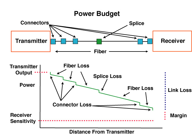
The following drawings show the power budget of a 2km hybrid multimode/singlemode link with 5 connections (2 connectors at each end and 3 connections at patch panels in the link) and one splice in the middle.

power budget

Link Budget for WDM and Amplified Transmissions over Single-mode Fibres

In the case of WDM transmissions, passive modules are used to multiplex and demultiplex various wavelengths respectively before and after the signal propagates along the fibre channel. These passive modules introduce additional insertion losses suffered by the signal transmitted.

Additionally, the signal may be amplified and compensated for dispersion, and in this case, the amplifier gain and the dispersion compensation unit’s loss need to be taken into account. Dispersion and OSNR (optical signal noise ratio) penalties suffered by the receiver shall be considered as well.

Therefore all the parametres needed for a proper link budget evaluation are:
● The minimum transmit power guaranteed (minTx), expressed in dB/m
● The minimum receive power required (minRx), expressed in dB/m
● The loss of optical connectors and adapters (L), expressed in dB
● The number of connectors and adapters (n)
● The normalized fibre loss (FL), expressed in dB/km
● The reach or distance to be achieved (d), expressed in km
● The loss of passive add/drop modules (A and D), expressed in dB
● The gain of the amplifier (G), expressed in dB
● The penalty suffered by the receiver (P), expressed in dB
● The loss of a dispersion compensation unit (DCU), expressed in dB With these parametres, (LB) is given as for previous cases:
● (LB) = (minTx) – (minRx)
And the total loss is expressed as follows:
● (TL) = n*(L) + d*(FL) + (A) + (D) – (G) + (DCU) + (P)
Here again, if LB is greater than TL, then the physical deployment is feasible. Please note that for simplicity, only one amplifier, one dispersion compensation unit, and one set of add/drop modules are considered in this example. If more devices are planned to be deployed, their loss or gain should be added or subtracted accordingly in order to calculate TL.

Link budget is a way of quantifying the link performance. And the performance of any communication link depends on the quality of the equipment being used. Thus, when evaluating a link budget, you are supposed to consider the types of applications, the reach to be achieved, as well as the types of optical fibres deployed. For more information about fibre optical link products, please visit FS.COM.

Erbium Doped Fibre Amplifier (EDFA) Used in WDM System

The capacity of fibre optical communication systems has undergone enormous growth during the last few years in response to huge capacity demand for data transmission. With the available wavelength division multiplexing (WDM) equipment, commercial system can transport more than 100 channels over a single fibre. However, increasing the number of channels in such systems will eventually result in the usage of optical signal demultiplexing components with greater values of optical attenuation. Besides, when transmitted over long distances, the optical signal is highly attenuated. Therefore, to restore the optical power budget, it is necessary to implement optical signal amplification. This article may mainly tell you  why EDFA is used in WDM system and how does it work.

Why Use EDFA in WDM System?

EDFA stands for erbium-doped fibre amplifiers, which is an optical amplifier that uses a doped optical fibre as a gain medium to amplify an optical signal. EDFA has large gain bandwidth, which is typically tens of nanometres and thus actually it is enough to amplify data channels with the highest data rates. A single EDFA may be used for simultaneously amplifying many data channels at different wavelengths within the gain region. Before such fibre amplifiers were available, there was no practical method for amplifying all channels between long fibre spans of a fibre-optic link. There are practically two wavelength widows C-Band (1530nm-1560nm) and L-Band (1560nm-1600nm). EDFA can amplify a wide wavelength range (1500nm-1600nm) simultaneously, which just satisfies the DWDM application, hence it is very useful in WDM for amplification.

How Does EDFA Work ?

The basic configuration for incorporating the EDFA in an optical fibre link is shown in the picture below. The signals and pump are combined through a WDM coupler and launched into an erbium-doped fibre (EDF). The amplified output signals can be transmitted through 60-100km before further amplification is required.

EDFA
Erbium-doped fibre is the core technology of EDFA, which is a conventional silica fibre doped with erbium ions as the gain medium. Erbium ions (Er3+) are having the optical fluorescent properties that are suitable for the optical amplification. When an optical signal such as 1550nm wavelength signal enters the EDFA from input, the signal is combined with a 980nm or 1480nm pump laser through a wavelength division multiplexer device. The input signal and pump laser signal pass through erbium-doped fibre. Here the 1550nm signal is amplified through interaction with doped erbium ions. This can be well understood by the energy level diagram of Er3+ ions given in the following figure.

EDFA

Where to Buy EDFA for Your WDM System ?

To ensure the required level of amplification over the frequency band used for transmission, it is highly important to choose the optimal configuration of the EDFAs. Before you buy a EDFA, keep in mind that the flatness and the level of the obtained amplification, and the amount of EDFA produced noise are highly dependent on each of the many parametres of the amplifier. FS provide many kinds of EDFAs, especially the DWDM EDFAs (shown in the picture below), which have many output options (12dBm-35dBm). Besides, they are very professional in optical amplifiers. Whatever doubts you have, they can give a clear reply.

EDFA

WDM Multiplexer Is an Ideal Component Optimised for WDM Aplications

Wavelength-division multiplexing (WDM) is a technology which allows multiple signals to be transmitted at different wavelengths over a single optical transmission medium. It can dramatically expand the total capacity of an optical network, for many signals are able to be transported simultaneously. This core technology makes optical network capacity to be gradually efficiently increased to meet the higher demand for bandwidth. To construct WDM networks, a wide range of optical components optimised for WDM applications are required to be researched and created. One of the important components is WDM multiplexer.

WDM multiplexer is an electronic device that uses WDM technology. It is able to combine light signals with different wavelengths coming from different fibrs on toe a single fibre. A multiplexer usually has two signal inputs, one control input and one output. The input end of a WDM multiplexer is coupler that combines all the inputs into one putout fibre. And each channel in a WDM multiplexer is designed to transmit a specific optical wavelength. For example, an 16-channel multiplexer would have the ability to combine sixteen different channels or wavelengths from separate optical fibres onto one optical fibre. And the separated signals will be recovered by another multiplexer called demultiplexer. The following picture shows how the signals are transported.

multiplexer and demultiplexer

WDM multiplexer is available with various configurations such as 2,4, 8, 16, 32, 64, etc. The types of multiplexers can be divided by channel spacing. They can be called CWDM multiplexers, wideband or crossband ones, and DWDM multiplexers, narrowband or dense ones. Compared to DWDM multiplexers, CWDM multiplexers combines signals at fewer channels for its larger channel spacing. CWDM multiplexers is usually with configurations such as 8, 16 and so on, while DWDM multiplexers is commonly with configurations including 32, 96, 128, etc. CWDM multiplexers are able to combine a broad range of wavelengths such as l310 nm and 1550 nm. DWDM multiplexers are able to combines wavelengths with 100 GHz channel spacing. It typically provides a broad range of wavelengths in 1.55-μm region within C-band.

WDM multiplexer, an advanced optical component, is widely used in optical links. It can increase connectivity and bandwidth of processing systems by interconnecting different channels. Most WDM multiplexers employ one of three technologies: arrayed waveguide grating (AWG), filter and dispersive element, primarily diffraction grating. Some multiplexers based on filters exhibit high insertion loss for devices with many channels, which makes them are not suitable in the application of multimode and bi-directional transmission. But the multiplexers with AWG technology offers many advantages over them including low cost for many channels, low loss, little crosstalk, and receiving much attention. With AWG technology, WDM multiplexer is ideal for the application of high throughput optical links in parallel processing and computing.

It is concluded that WDM multiplexer with WDM technology is a key component in optical links and even in the high throughput optical links.