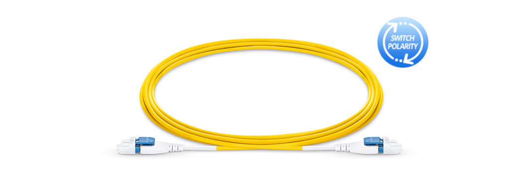
The data centre is moving towards high speed and high density. How to build more optical fibre cables in limited space is becoming increasingly severe. In this case, FS.COM introduced a new-type product suitable for high density cabling requirement—polarity switchable LC uniboot cable. It’s the preferred option for high density data centre connection today. Its largest feature is switchable polarity, designed to eliminate the need for dual zip cords and reduce overall bulk cabling by 50%. But do you know about polarity switchable LC uniboot cable? What are the features of it and how to reverse the polarity? You may find answer in this post.
LC uniboot fibre patch cables are designed for high density applications in data centre environment. Generally, the LC uniboot patch cord is designed with a polarization method that can help users easily reverse the fibre polarity. In addition, the LC uniboot fibre patch cable can reduce cable management space comparing to standard patch cord as it places both simplex fibres into one jacket while still terminating into a duplex LC connector. Similar to the standard patch cord, single-mode and multimode versions are available in LC uniboot patch cables.
FS polarity switchable LC uniboot cables feature high density. They are used to connect switches or network devices in fibre networks directly or interconnect structured cabling systems in a fibre network. Besides, FS uniboot fibre patch cable has the following highlights.
- Easy polarity reversal: Polarity changes can be made in the field quickly, without the use of tools, to the correct fibre mapping polarity.
- “All in One” international quality cable assemblies: FS uniboot fibre patch cable has passed IEC61300-3-35 end-face standard, EIA/TIA-455-171A attenuation standard and CE, etc. providing customers with the outstanding, standards-compliant products and services.
- LC licence compliant & 0.2dB IL: The worldwide licence and low insertion loss keep your network running fast and smooth.
- 2.0mm round cable design: 2.0mm thin diametre allows the polarity to be switched from A-B to A-A without any tools.
- More fibre options: OM3, OM4, and OS2.
- Space saving: It can save the space of cassettes and cable management by 68%.
As we know, for traditional cabling systems using single fibre connectors, maintaining polarity requires that the “A” transmits signal and at the same time the “B” receives signal. But duplex patch cords used to complete serial duplex pair connections available in two types, depending on which polarity technique is used— “A-to-B” patch cord for “straight-through” wiring and “A-to-A” patch cord for “crossover”wiring. Thus, polarity reversal is usually required during fibre optic cabling.
However, polarity reversal of traditional LC patch cable is very inconvenient and annoying since some minor mistakes could lead to various troubles. Therefore, FS.COM developed the LC uniboot cable that is easier for polarity reversal, without having to re-terminate the connectors. Here two methods of polarity reversal are introduced as follows.

From the above picture, we can see that we can use just 3 steps to reverse polarity. Type one (the left one):
1. Open connector top.
2. Switch the polarity from A-B to A-A.
3. Close connector top.
Type two (the right one):
1. Open connector top.
2. Rotate connector 180 degree to exchange the position.
3. Close connector top.
To address the increasing demand for high density applications and smaller fibre cable, the LC uniboot fibre patch cable is designed to help cut down cabling space and provide more effective polarity reversal solution. I hope this article could help you choose the proper product for high density cabling. FS.COM not only provides polarity switchable LC fibre patch cable, but also provides bend insensitive fibre patch cable which is also a high density cabling application. Welcome to consult with customer service for more details.


