Category Archives: Fiber To The Home

A compelling treatment of FTTH

Fibre Patch Panel Termination

It seems that we have already known that the fibre patch panel is the bridge of fibre patch cables. Fibre patch panel, also known as fibre distribution panel, serves as a convenient place to terminate all the fibre optic cable running from different rooms into the wiring closet and provides connection access to the cable’s individual fibres. Fibre patch panels are termination units, which are designed with a secure, organised chamber for housing connectors and splice units.

How Does Patch Panel Termination Units Works?

We know that there are two major termination solutions for fibre cable: field terminated and pre-terminated. The pre-termination, with most devices terminated by the manufacturers in advance, requires less efforts when installing than field termination does. Therefore, this post is going to offer a glimpse into the field termination which describes the termination of the fibre optic cable in the field or the termination after installation.

Fibre Patch Panel Termination Procedure

In the termination process, the fibre optic cable need to be pulled between two points, then connectors will need to be attached and then connected to a patch panel. In addition, before they can be attached to a panel, connectors need to be attached to each individual strand, and a variety of tools will be needed. With field termination, we can determine the cable length accordingly, and fibre optic bulk cable is very easily to pull from either end of the installation circuit.
To carry out the termination, such tools are needed as fibre optic enclosure, fibre cable, patch panel, cable ties, connector panels, permanent marker, fibre optic stripper, cleaver, metric ruler and rubbing alcohol.

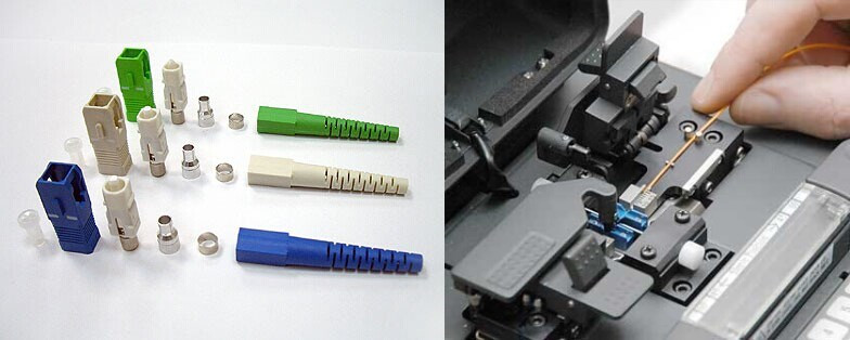
To terminate the cable, first slide the boot onto the fibre. Strip the fibre to at least about an inch and a half . Place a mark at 15.5 mm for ST and SC connectors or at 11.5 mm for LC connectors. Clean the stripped fibre with an alcohol wipe and remove any debris. Set the stripped fibre into the cleave and cleave it. Insert the cleaved fibre into the rear of the connector until the mark align with the back of the connector body. Slight the boot up and over the rear of the connector body. After the termination, transmission testing of assemblies need to be performed.

fiber optics termination
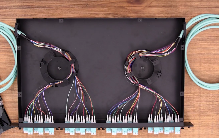
In the final fibre patch panel termination, first, open the front and rear door of the patch panel, and remove the covers. Remover the inter stain relief bracket. Second, use cable ties to put the cables on the bracket. The fibres should be put inside the clips on the tray to segregate the fibres from A and B slots. Put the patch panel into the panels clips. Take the excess fibre slack into the slack management clips. Make a bend in the fibre to maintain slight pressure on the connection.

fix the cover

Conclusion

The processes in the device connection and cable management are linking with each other that missing any or failure in any one will result in the imperfect system, or even the damage. If we own a fibre patch panel, we should make full use of its termination function. The products provided by FS,COM enable you to perfect your cabling system.

Wall Mount VS Rack Mount Patch Panel

Patch panels are termination units, which are designed to provide a secure, organised chamber for housing connectors and splice units. Its main function is to terminate the fibre optic cable and provide connection access to the cable’s individual fibres. Patch panels can be categorised into different types based on a few different criteria. Last time, we have shed light on the copper and fibre patch panel and now let’s learn a different pair of it, namely wall mount patch panel and rack mount patch panel.

Wall Mount Patch Panel

As the name suggests, wall mount patch panel is a patch panel fixed on the wall.The wall mount patch panels are designed to provide the essential interface between multiple fibre cables and optical equipment installed on the customer’s premises. The units offer networking and fibre distribution from the vault or wiring closet to the user’s terminal equipment.

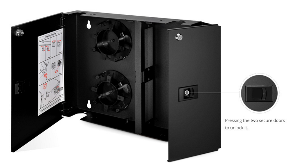
This kind of patch panel consists of two separate compartments. As shown below, the left side is used for accommodating outside plant cables entering the building, pigtails and pigtail splices. Whereas, the right side is designed for internal cable assembly networking. And both sides have a door secured with a quarter turn latch.

wall mount patch panel

Rack Mount Patch Panel

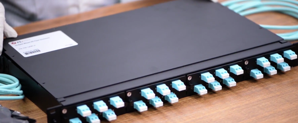
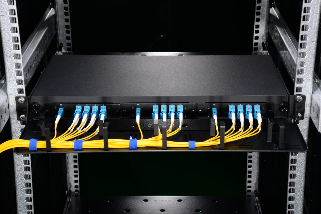
The rack mount patch panel usually holds the fibres horizontally and looks like a drawer. Rack mount panel is designed in 1U, 2U, 4U sizes and can hold up to 288 or even more fibres. They can be mounted onto 19″ and 23″ standard relay racks. The rack mount enclosures include two kinds. One is the slide-out variety and the other incorporates a removable lid. As for the latter one, the tray can be pulled out and lowered to 10 degree working angle or even further 45 degree working angle to provide ease of access for maintenance or installation work.

rack mount patch panel

Wall Mount VS Rack Mount Patch Panel

  • Installation

When installing wall mount patch panels, users need to leave at least 51mm additional space on each side to allow opening and removing the doors. Although it can be easily mounted to the wall by using the internal mounting holes, four screws are required when it is attached to a plywood wall, expansion inserts with wood screw for concrete walls and “molly bolts” for sheet rock. However, the installation of a rack patch panel just needs four screws without drilling the wall.

  • Space Occupation

Thinking from another perspective, the advantage of wall mount patch panels is that they allow you to optimise your work space by keeping equipment off floors and desks,which is superior to the rack mount patch panel.

  • Application

Both panels can be applied to Indore Premise Networks, Central offices (FTTx), Telecommunication Networks, Security Surveillance Applications, Process Automation & Control, Systems and Power Systems & Controls, while the rack mount patch panel has an advantage over the wall mount patch panel in that it can be applied to Data Centres.

Conclusion

To sum up, patch panels are available in rack mounted and wall mounted and are usually placed near terminating equipment (within patch cable reach). Both types can provide an easy cable management in that the panel ports can be labeled according to location, desktop number,etc. to help identify which cable from which location is getting terminated on which port on the patch panel, and changes can be made at the patch panel. The world-wide renown FS.COM can provide you the best quality rack mount and wall mount patch panel. Buyers are welcome to contact us.

A Wise Decision to Choose DWDM Mux/DeMux

The advent of big data requires for highly efficient and capable data transmission speed. To solve the paradox of increasing bandwidth but spending less, WDM (wavelength division multiplexing) multiplexer/demultiplexer is the perfect choice. This technology can transport extremely large capacity of data traffic in telecom networks. It’s a good way to deal with the bandwidth explosion from the access network.

WDM

WDM stands for wavelength division multiplexing. At the transmitting side, various light waves are multiplexed into one single signal that will be transmitted through an optical fibre. At the receiver end, the light signal is split into different light waves. There are 2 standards of WDM: coarse wavelength division nultiplexing (CWDM) and dense wavelength division multiplexing (DWDM). The main difference is the wavelength steps between the channels. For CWDM this is 20nm (course) and for DWDM this is typically 0.8nm (dense). The following is going to introduce DWDM Mux/Demux.

DWDM Technology

DWDM technology works by combing and transmitting multiple signals simultaneously at different wavelengths over the same fibre. This technology responds to the growing need for efficient and capable data transmission by working with different formats, such as SONET/SDH, while increasing bandwidth. It uses different colors (wavelength) which are combined in a device. The device is called a Mux/Demux, abbreviated from multiplexer/demultiplexer, where the optical signals are multiplexed and de-multiplexed. Usually demultiplexer is often used with multiplexer on the receiving end.

Mux/Demux

Mux selects one of several input signals to send to the output. So multiplexer is also known as a data selector. Mux acts as a multiple-input and single-output switch. It sends optical signals at high speed over a single fibre optic cable. Mux makes it possible for several signals to share one device or resource instead of having one device per input signals. Mux is mainly used to increase the amount of data that can be sent over the network within a certain amount of time and bandwidth.

Demux is exactly in the opposite manner. Demux is a device that has one input and more than one outputs. It’s often used to send one single input signal to one of many devices. The main function of an optical demultiplexer is to receive from a fibre consisting of multiple optical frequencies and separate it into its frequency components, which are coupled in as many individual fibres as there are frequencies.

mux-and-demux

DWDM Mux/Demux modules deliver the benefits of DWDM technology in a fully passive solution. They are designed for long-haul transmission where wavelengths are packed compact together. FS.COM can provide modules for cramming up to 48 wavelengths in 100GHz grid(0.8nm) and 96 wavelengths in 50GHz grid(0.4nm) into a fiber transfer. ITU G.694.1 standard and Telcordia GR1221 are compliant. When applied with Erbium Doped-Fiber Amplifiers (EDFAs), higher speed communications with longer reach (over thousands of kilometres) can be achieved.

Currently the common configuration of DWDM Mux/Demux is from 8 to 96 channels. Maybe in future channels can reach 200 channels or more. DWDM system typically transports channels (wavelengths) in what is known as the conventional band or C band spectrum, with all channels in the 1550nm region. The denser channel spacing requires tighter control of the wavelengths and therefore cooled DWDM optical transceiver modules required, as contrary to CWDM which has broader channel spacing un-cooled optics, such as CWDM SFP, CWDM XFP.

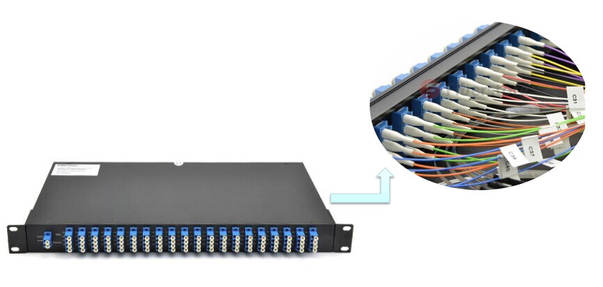
DWDM Mux/Demux offered by FS.COM are available in the form of plastic ABS module cassette, 19” rack mountable box or standard LGX box. Our DWDM Mux/Demux are modular, scalable and are perfectly suited to transport PDH, SDH / SONET, ETHERNET services over DWDM in optical metro edge and access networks. FS.COM highly recommends you our 40-CH DWDM Mux/DeMux. It can be used in fibre transition application as well as data centre interconnection for bandwidth expansion. With the extra 1310nm port, it can easily connect to the existing metro network, achieving high-speed service without replacing any infrastructure.

DWDM MUX DEMUX

Conclusion

With DWDM Mux/DeMux, single fibres have been able to transmit data at speeds up to 400Gb/s. To expand the bandwidth of your optical communication networks with lower loss and greater distance capabilities, DWDM Mux/DeMux module is absolutely a wise choice. For other DWDM equipment, please contact via sales@fs.com.

Available Interconnect Solutions for FTTH Drop Cables

FTTH, short for fibre to the home, is the installation and use of optical fibre from a central point directly to individual buildings such as residences, apartment buildings and businesses to provide unprecedented high-speed Internet access. In determining the best solution for a particular FTTH deployment, providers must first decide between splices and connectors. Then, they must choose the best splice or connector for the particular circumstances of deployment. This article explores the available interconnect solutions for FTTH drop cables and discusses their advantages and disadvantages in various deployment circumstances.

FTTH

Splice vs Connector

Before deploying a FTTH network, providers must first decide whether to use a splice, which is a permanent joint, or a connector, which can be easily mated and un-mated by hand. Both splices and connectors are widely used at the distribution point. At the home’s optical network terminal (ONT) or network interface device (NID), either a field-terminated connector or a spliced-on factory-terminated connector can be used.

Splices enable a transition from 250micron drop cable fibre to jacketed cable with high reliability and eliminates the possibility of the interconnection point becoming damaged or dirty. Splices are most appropriate for drop cables dedicated to a particular living unit where no future fibre rearrangement is necessary, such as in a greenfield or new construction application where the service provider can easily install all of the drop cables during the living unit construction.

Connectors are easier to operate and provide greater network flexibility than splices, because they can be mated and unmated repeatedly, allowing them to be reused over and over again. Connectors also provide an access point for network testing. However, connectors cost more than splices although network rearrangement is much cheaper. Therefore, providers must weigh the material cost of connectors along with the potential for contamination and damage against their greater flexibility and lower network management expense.

Splice vs Connector

Choosing the Right Splice

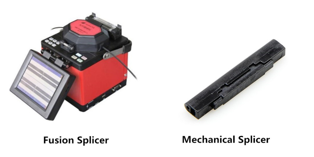
Splicing technology for FTTH deployment falls into two major categories: fusion and mechanical.

Fusion splicing is considered to be a solution for FTTH drop splicing, especially considering it provides a high quality splice with low insertion loss and reflection. However, fusion splicing is expensive and requires trained technicians to operate. It is time-consuming and the slow installation speed hinders its status as the preferred solution. Fusion splicing is best suited for companies that have already invested in fusion splicing equipment and do not need to purchase additional splicing machines.

Mechanical splices can perform well in many environments and have been successfully deployed around the world in FTTH installations. A typical mechanical fibre optic splice includes a small plastic housing with an aluminum alloy element to precisely align and clamp fibres. An index matching gel inside the splices maintains a low-loss optical interface, which results in an average insertion loss of less than 0.1 dB.

Splicer

Choosing the Right Connector

According to the drop cables used, connectors can be divided into two types: factory-terminated and field-terminated.

Factory-terminated
Factory-terminated drop cables can provide high-performing, reliable connections with low optical loss. Factory termination also keeps labor costs low by reducing installation time. An excellent application is a patch cord that connects a desktop ONT to a wall outlet box inside the living unit. A key failure point in the network is when the end user accidentally breaks the fibre in the cable that connects the desktop ONT. If this occurs, the patch cord can be easily replaced. However, factory-terminated cables can be expensive compared to field-terminated alternatives.

Field-terminated
Many providers prefer field-terminated connectors where the installation can be customised by using a reel of cable and connectors, such as fuse-on connectors and mechanical connectors. For example, fuse-on connectors use the same technology as fusion splicing to provide the highest level of optical performance in a field-terminated connector. By incorporating the fusion splice inside the connector, the need for a separate splice tray has been eliminated. However, fuse-on connectors share many of the same drawbacks as fusion splicing. They require expensive equipment, highly trained technicians, and packing and unpacking time, and a power source, ratcheting up installation costs. However, mechanical connectors can provide alternatives to fuse-on connectors for field installation of drop cables.

Summary

The drop cable interconnect solution comprises a key component of an FTTH network. Reliable broadband service depends upon robust connections at the distribution point and the NID/ONT. Choosing the right connectivity product can result in cost savings and efficient deployment while providing reliable service to customers. Globally, most FTTH drop cable installations have been and continue to be field-terminated on both ends of the cable with mechanical connectivity solutions.

Basic Knowledge about Ethernet

Nowadays, billions of file cabinets and mountains of papers stored in computers need to be transmitted at high speed with great efficiency. Computer networking technologies are key to meet this demand, allowing computers on the internet to send and receive information easily. This article will introduce the network technology: Ethernet which is widely used nowadays.

Ethernet is a family of computer networking technologies for local area networks (LANs) and metropolitan area networks (MANs), connecting more than 85 percent of the world’s LAN connected PCs and workstations. It is a link layer protocol in the TCP/IP stack, describing how networked devices transmit data on the same network segment and how to put data out on the network connection. Ethernet was commercially released in 1980 and first standardized in 1983 as IEEE 802.3. Its standards have been updated to embrace new media, higher transmission speeds and changes in frame content such as the new standard 802.3af defining Power Over Ethernet [POE] crucial to most Wi-Fi and IP telephony deployments.

Ethernet

Ethernet was initially designed to run over coaxial cables but has been updated to used for twisted pair cables and fibre optical fibres over years. The most commonly installed Ethernet systems are called 100 BASE-T (the “BASE-T” part means the systems use twisted-pair cabling) which provides transmission speeds up to 100Mbps. It is typically used for LAN backbone systems, supporting workstations with 10BASE-T cards. Another widely used one is Gigabit Ethernet which is primarily carried on optical fibre with very short distances possible on copper media. It provides an even higher level of backbone support at 1000 Mbps or 1 Gbps. With the increasing of data transfer rates, the standards: 10 Gigabit Ethernet and 100 Gigabit Ethernet are available. Their data rates reached up to 10 gigabits per second and even 100 gigabits per second respectively, making them be good solutions to deliver high bandwidth in LANs.

QQ截图20150525174629

100GBASE-LR4 CFP2 Optical Transceiver Module

It is concluded that Ethernet has evolved to provide excellent performance and network intelligence. As Ethernet data transfer rates are excepted to be increased to 400 Gbit/s by early 2017, Ethernet will be the most potential network technology in the future for its high-speed data transmission.

Fiberstore offers a wide range of products for 10GbE or 100 GbE applications such as the new product: 100GBASE-LR4 CFP2 Optical Transceiver module. The optical transceiver offers smaller size and lower power consumption for data centre networking, enterprise core aggregation, and service provider transport applications. For more information, please visit www.fs.com.

CWDM Cost Efficient Transport in Short-haul Networks

CWDM-technology

CWDM Technology

In the field of telecommunications, data centre connectivity, video transport, fibre optic cabling is highly desirable for today’s communication needs due to the enormous bandwidth availability. As fibre cabling is sometimes expensive for people especially individuals to use, wavelength division multiplexing (WDM) is highly advisable for it can expand the capacity of fibres. This article will depict one kind of WDM: coarse wavelength division multiplexing (CWDM or Coarse WDM) which works efficiently with lower cost in short-haul networks in comparison with DWDM (Dense WDM).

CWDM is a method of combining multiple signals on laser beams at various wavelengths for transmission along fibre optic cables. Compared to DWDM which is a more tightly packed WDM system, CWDM has larger channel spacing, having fewer wavelengths be transported on the same fibre. For instance, CWDM typically has channels at wavelengths spaced 20 nanometres (nm) apart, compared with 0.4 nm spacing for DWDM. DWDM can typically transmit from 32 to 128 channels by using erbium-doped fibre amplifiers to boost the signal over long distances, which makes it ideal for long-haul networks. In contrast, CWDM can only transmit a maximum of 18 channels with large spacing between channels, making optical amplifiers not able to be used in CWDM system. So CWDM is typically deployed at short-haul networks.

Cost-Comparison-of-WDM-Technologies

Cost Comparison of WDM Technologies

Due to its broader channel spacing, CWDM has a cost advantage over DWDM. CWDM systems spread less precise lasers over a larger range of wavelengths with consuming less power with low losses. For example, both DWDM and CWDM utilise Distributed Feedback Lasers (DFB). However, DWDM requires the larger cooled DFB lasers because laser wavelengths drift about 0.08 nm/°C with temperature. CWDM uses DFB lasers that are not cooled because laser wavelengths drift about 6nm over the range of 0-70°C and the lasers’ tolerance (extent of wavelength imprecision or variability) in a CWDM is up to ±3 nm. The use of uncooled lasers causes lower power consume, which has positive financial implications for systems operators. For instance, the cost of battery is minimized with the decreasing of power consume, which reducing operating costs.

It is concluded that CWDM is the technology of choice for cost efficiently transporting data traffic in short-haul networks. And as the demand for bandwidth is pushed to the edge of the network, the need for low-cost transport systems is imperative.

QQ截图20150518181345

CWDM Transceivers

FS offers a wide range of CWDM products such as CWDM MUX DEMUX with low cost, CWDM OADM with various configurations, CWDM Transceivers (SFP, SFP+, XFP, GBIC, X2, XENPAK) supporting 155Mbps to 10Gbps data transmissions, etc. Compatible CDWM transceivers are strongly recommended for you. There are CWDM transceivers of famous brands such as Cisco, HP, Juniper, etc. All these CWDM transceivers are of high quality and capacity to be applied to transport data traffic with low cost. For more information, you can visit FS online shop.

Fluke Networks AirCheck Wi-Fi Tester

As one of the global-leading providers, Fluke offers network testers intensively trusted by leading industry professionals when they need to solve the most difficult issues and emerging challenges in data centres, mobility, and unified communications and WLAN security. This article will depict one kind of its network testers known as Fluke Networks AirCheck Wi-Fi Tester.

Introduction of Fluke Networks AirCheck Wi-Fi Tester

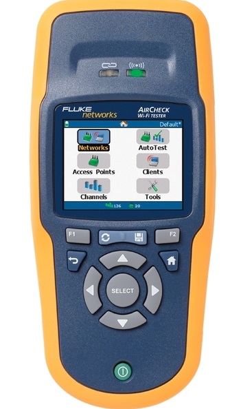
AirCheck Wi-Fi Tester is a simple-to-use, handheld wireless tester used for verifying and troubleshooting 802.11 a/b/g/n network availability, connectivity, and security quickly. Its intuitive interface allows you to promptly see wireless network usage and easily determine if it’s Wi-Fi traffic or non- Wi-Fi interference. It is an essential tool of checking wireless environment, enabling you to identify and locate APs whether authorized or rogue. And it can document your troubleshooting session and create professional-quality reports fully, enabling fast trouble ticket resolution or problem escalation.

Fluke network tester

Features of Fluke Networks AirCheck Wi-Fi Tester

Some features of it are listed in details, which assures that you will have a further and clearer understanding of it.

  • Supports 802.11a/b/g/n/ac with instant-on operation powering up in less than three seconds and automatically starts discovering networks, access points (APs), and channel activity
  • Get answers fast through one-button Auto Test which provides a pass/fail indication of the wireless environment and identifies common problems
  • Identifies security settings for each Network and Access Point: Open, WEP, WPA, WPA2, and/or 802.1x
  • Pinpoints Wi-Fi traffic and interference to show how much of each channe’s bandwidth is consumed by 802.11 traffic and interference
  • Connects networks or specific APs using WEP, WPA, WPA2, and/or 802.1x to verify connectivity and network access inside and outside the firewall
  • Robust and in-depth WLAN connection tests – from probing to DHCP request to ping
Fiberstore Fluke Networks AirCheck Wi-Fi Tester Solution

Fiberstore offers five modules of network AirCheck Wi-Fi testers at reasonable price with quality guarantee. Details are shown on the following sheet.

Module # Accessories Description
AirCheck–LE AirCheck Wi-Fi Tester for Law Enforcement includes: AirCheck tester, AirCheck holster, External directional antenna, Auto charger and AirCheck Getting Started Guide for Law Enforcement
ACK-LRAT2000 Network Tech Troubleshooting Kit w/ACK,LRAT-2000 includes: AirCheck tester, LinkRunner AT 2000 tester, AirCheck external directional antenna, spare Li-ion battery for either AirCheck or LinkRunner, IntelliTone Pro 200 probe, WireView 2-6 cable ids, LinkRunner AT holster, AirCheck holster and deluxe carrying case
ACK-LRAT-CIQ Ultimate Network Tech Troubleshooting Kit w/ACK,LRAT-2000,CIQ includes: AirCheck™ tester, LinkRunner AT 2000 tester, AirCheck external directional antenna, spare Li-Ion battery for either AirCheck or LinkRunner, IntelliTone Pro 200 probe, WireView 2-6 cable ids, LinkRunner AT holster, AirCheck holster and deluxe carrying case and CableIQ™ Qualification tester Fluke Networks
ES2-PRO-SX/I-ACK EtherScope Series 2 LAN WLAN SX Fibre ITO + AirCheck including: EtherScope Series 2 LAN and WLAN with fibre and ITO options; and AirCheck Wi-Fi Tester
ES2-PRO-SXI-LR-ACK EtherScope E S2 LAN WLAN SX Fibre ITO + LRPRO + AirCheck-Kit including: EtherScope E Series 2 LAN and WLAN with fibre and ITO options; LinkRunner Pro with Reflector, Lithium Ion battery, and software case; and AirCheck Wi-Fi Tester with extra Lithium Ion battery, directional antenna and hard case

Optical Transport Platforms – Make optical transport network more cost-effective

Overview
With the development of optical transport network, especially the improvement of WDM (Wavelength Division Multiplexing) technology, more and more components and devices should be put into use in the network to support it. However, upgrading the existing architecture of your network is often a difficult problem. We had to pay too much to buy new devices and also had to pay an addtional cost to rebuild your cabling. We can imagine how much difficulty we will have to do. So, how to solve this problem? In this case, “optical transport platform” may be one of your best choice.

In fact, we do not need to stack a various of equipment to respectively achieve the various commands. In contrast, we use the equipment with high integration to achieve it. For example, if an optical transport platform combines the OTN (Optical Transport Network) and WDM features, it can enable customers to integrate multiple access transport networks into a single network. Moreover, the optical transport platform is easy for upgrading by renewing the system control board. Nowadays, optical transport platforms are widely used in the fields of telecom operation, broadcasting, electric power, and information safety etc. Additionally, it is a reliable, simplified and timely redundancy solution for data center.

Advantages of Using Optical Transport Platform
The emergence of optical tranport platform is the result of high speed data transmission. In general, optical transport platform features of transparent transmission of all services over a single network, saving fiber resource, as well as designing with high reliability.

  • Minor initial investment, low operating costs, always scalable
  • Cost-efficient usage of fiber optic capacities
  • High performance location networking and computer center coupling

It helps solve the following problems that are faced by access transport networks:

  • How to realize unified transmission of the 100M – 10G services by using the equipment with high integration?
  • How can the network realize long distance transmission with fewer nodes?
  • How to reduce maintenance and network operation costs?
  • How to effectively lower the ever-increasing energy consumption of equipment, cut down electricity costs, and promote the image of the enterprise?
  • How to realize the smooth upgrade of a network and safeguard the investments?

Applications of Optical Transport Platform
Optical transport platform is an important part of optical tranport network. The application of different line cards can satisfy different requirements, such as Long-haul transport, Ethernet demarcation and conversion or unidirectional WDM transmission etc. In addition, optical transport platform is used in CATV optical transport through adding the corresponding line cards.

FS.COM Optical Transport Platform Solution
Fiberstore FS-OEO800 series optical transport platform products include optical fiber link wavelength converters, optical system control boards, optical switch line protection cards, as well as FS-OEO800 optical transport platform chassis. Meanwhile, the FS-OEO800 series is a powerful custom product line supported by Fiberstore R&D team. We can supply customized service cards and transport platforms to meet your special needs, and design transport platforms’ label and packaging for your company. The FS-OEO800 Optical Transport Platform is purposely built to help network operators accommodate next-generation bandwidth and service requirements while reducing operational and capital expense.

Product Recommendation:

Product Image Model # Description
Fiberstore optical transport platform chassis FS-OEO800-I 4 Slots 19″ 1U FS-OEO800-I Comprehensive Optical Transport Platform Chassis
FS-OEO800-SCF 2 x 100M Ethernet Ports And 2 x SFP Module Slots System Control Board

For more information, please visit our official website or contact us over E-mail: sales@fs.com.

how mpo/mtp cable to be tested

To understand the challenges of MPO cable validation, it’s necessary to understand MPO cables and how they’re tested in the field. An MPO connection is about the size of a fingernail and contains 12 optical fibers, each less than the diameter of a human hair – and each one needs to be tested separately. That traditionally means the use of a fan-out cord to isolate each fiber, followed by tedious manual testing, tracing, and error-prone calculations.

Testing and determining fiber polarity is another challenge. The simple purpose of any polarity scheme is to provide a continuous connection from the link’s transmitter to the link’s receiver. For array connectors, TIA-568-C.0 defines three methods to accomplish this: Methods A, B, and C. Deployment mistakes are common because these methods require a combination of patch cords with different polarity types

So what would a proper MPO test look like? The answer is simple: Test all 12 fibers – the whole cable – simultaneously and comprehensively (including loss, polarity, etc.). That sort of test capability changes the fiber landscape, enabling installers and technicians to efficiently validate and troubleshoot fiber – flying through the process by tackling an entire 12-fiber cable trunk with the push of a button.

The tools to perform this type of test are just emerging on the market, and promise to reduce the time and labor costs up to 95% over individual fiber tests (according to internal research based on the average list of standard competitive products). Characteristics to look for in such a tool include:

An onboard MPO connector to eliminate the complexity and manual calculations associated with a fan-out cord.
A single “Scan All” test function that delivers visual verification via an intuitive user interface for all 12 MPO fibers in a connector.
Built-in polarity verification for end-to-end connectivity of MPO trunk cables.
“Select Individual Fiber” function that enables the user to troubleshoot a single fiber with more precision.
Demand for fast and reliable delivery of critical applications is driving data center technology to evolve at an ever-increasing pace. And that insatiable need for bandwidth ensures that the integrity of the data center has become inextricably linked to the strength of the fiber cabling infrastructure. The growing use of MPO fiber trunks – and the migration from 10-Gbps to 40/100-Gbps connections – means that it’s time to stop the cumbersome verification of individual fibers. After all, it’s a single MPO connection. You should be able to test it as one.

You can buy fiber optic jumpers with mpo/mpo connectors  from FiberStore now!

Municipal Fiber optic networks

The city where I live, Palo Alto has a long tradition of providing municipal utility services (that is, electricity, water, gas, etc) to its residents. For the past several years the city has been considering implementing a municipal fiber optic system which would permit residents to have fiber optic cable link directly to their houses which provided television, telephone and Internet services (at very high bandwidths). Naturally, the incumbent service providers (cable and phone) strongly lobby against such moves (for precisely the same reasons these companies wish to be monopolists in the first place.) The incumbents have sabotaged municipal FTTH fiber efforts in the past — specifically in the “tri-cities” region in Illinois, around the far west suburbs of Chicago.

In this Sunday’s Mercury News, there’s an article which discusses the city’s plan to make a final feasibility study of the project and a recommendation to the city council. Even if the city council votes in favor of the project, there will be a city wide referendum, since fiber optic cable prices would require millions of dollars in bonds to finance.

As a resident of Palo Alto, as well as a technology advocate, I’m rather strongly in favor of such a move by the city, even though it carries some financial risk (if the fiber optic plan flops, the city would have to raise its rates for other utilities).

At last there might be a means of transmission which is separated from the fiber optic cable providers, something that the local cable and phone companies absolutely refuse to provide.

Imagine a network with massive amounts of bandwidth where multiple companies competed to send content down that connection to a consumer. How would this be anything but a win-win situation for everyone? The city sells the bandwidth to many different companies, consumers have lots of choices in content providers, and the content providers are collecting revenue for their content — and that’s the whole point anyway isn’t it?

SOURCE: http://it.toolbox.com