Category Archives: WDM System

DWDM Techonology in Long-haul Optical Networks

In twenty-first century, there is a growing volume of data traffic which requires a higher bandwidth capacity. But this explosion in consumer demand for bandwidth makes long-haul networks cop with fibre exhaust. To respond to this explosive growth in bandwidth demand, many long-haul providers use dense wavelength division multiplexing (DWDM) technology to enhance the capacity of propagating data.

DWDM wavelength

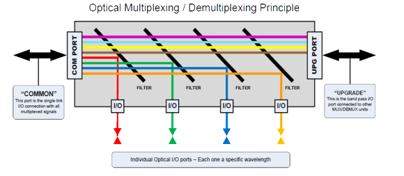
Wave Division Multiplexing: Light in different colors can be combined on the same fibre

DWDM Solution — Efficient for Long-haul Provider

DWDM is an efficient solution for long-haul providers. It can increase the capacity of embedded fibre by first assigning incoming optical signals to specific frequencies within a designated frequency band and then multiplexing the resulting signals out onto one fibre. Compared to CWDM (coarse wavelength division multiplexing), DWDM has smaller channels spacing, enabling more signals with higher precision to be combined on the same fibre. It is typically used for long-haul system for its more channels to transport data. DWDM typically has the capability to transport up to 96 channels (wavelengths) in what is known as the Conventional band or C-band spectrum. Fiberstore provide DWDM Mux/Demux various from 4 channels to 96 channels. For better use at present and in the future, we offer plug-in FMU DWDM Mux/Demux (Check FMU DWDM Mux/Demux). With the advancement of DWDM technology, even 160 channels (wavelengths) can be transported within the same fibre, which allows as many as signals be transported simultaneously. DWDM can also combine multiple optical signals, which makes them be amplified as a group and transported in high speed and large volume. So DWDM technology is one of the best choices for transporting extremely large amounts of data traffic over metro or long distances in optical networks.

dwdm wavelength region

Wavelength Regions

DWDM Solution — Economical for Long-haul Provider

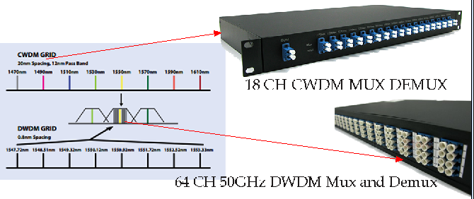
DWDM technology is also an economical solution for long-haul providers. A DWDM infrastructure can increase the distance between network elements, benefiting long-haul providers who look to reduce their initial network investments significantly. The fibre optic amplifier component of the DWDM system also enables long-haul providers to save costs without by taking in and amplifying optical signals without converting them to electrical signals. Furthermore, DWDM can provide a broad range of wavelengths in 1.55-μm region within C-band, which is showed in the picture “Wavelength Regions”. With a DWDM system multiplexing more wavelengths on a singer fibre, carriers can decrease the number of regenerators in a long-distance networks, resulting in fewer interruption and improved capacity with less loss.

Proven to be the optimal way of combining advanced functionality with cost efficient transport, DWDM technology is also friendly-used. The long-haul providers can integrate the DWDM technology easily with existing equipment in the network for the interface is bit-rate and format independent. And as continuous growth in data traffic, the long-haul providers will have an increasing reliance on improved DWDM technology to ensure good capacity of data transmission.

FS.COM DWDM Solution

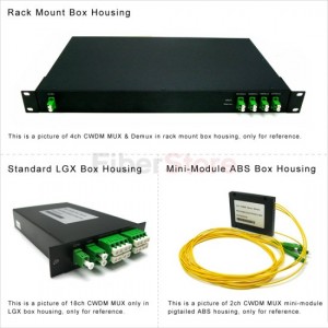
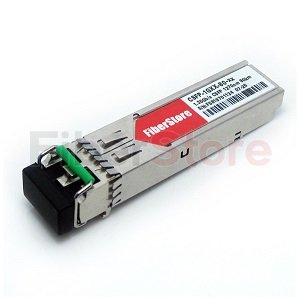
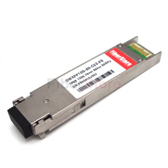
Fiberstore supplies a complete series of WDM optical network solutions such as multiplexers, amplifiers, transceivers, etc. Especially, Fiberstore produce and stock for a full range of DWDM products to help build and expand fibre optic networks. For example, Fiberstore offers DWDM MUX/DEMUX Modules with 50GHz/100GHz/200GHz channel spacing, DWDM OADM modules with various configurations and DWDM Transceivers (SFP, SFP+, XFP, GBIC, X2, XENPAK) supporting 155Mbps to 10Gbps data transmissions.

Optical Multiplexing for High Speed Communication Systems

Introduction

Optical transmission uses pulses of light to transmit information from one place to another through an optical fibre. The light is converted to electromagnetic carrier wave, which is modulated to carry information as the light propagates from one end to another. The development of optical fibre has revolutionized the telecommunications industry. Optical fibre has replaced other transmission media such as copper wire since inception, and is mainly used to wire core networks. Today, optical fibre has been used to develop new high speed communication systems that transmit information as light pulses, examples are multiplexers/demultiplexers using the optical multiplexing technology.

What is Multiplexing?

Multiplexer (Mux) is hardware component that combines multiple analog or digital input signals into a single line of transmission. And at the receiver’s end, the multiplexer is known as DeMultiplexer (DeMux)—performing reverse function of multiplexers. Multiplexing is therefore the process of combining two or more input signals into a single transmission. At receiver’s end, the combined signals are separated into distinct separate signal. Multiplexing enhances efficiency use of bandwidth. Here is a figure which shows the principle of optical multiplexing/demultiplexing.

Principle of Optical Multiplexing and DeMultiplexing

Optical Mux and DeMux are required to multiplex and demultiplex various wavelengths onto a single fibre link. Each specific I/O will be used for a single wavelength. One optical filter system can act as both Mux and DeMux. Optical Mux and DeMux are basically passive optical filter systems, which are arranged to process specific wavelengths in and out of the transport system (usually optical fibre). Process of filtering the wavelengths can be performed using Prisms, Thin Film Filter (TFF), and Dichroic filters or interference filters. The filtering materials are used to selectively reflect a single wavelength of light but pass all others transparently. Each filter is tuned for a specific wavelength.

Components of Optical Multiplexer

Generally, an optical multiplexer consists of Combiner, Tap Couplers (Add/Drop), Filters (Prisms, Thin film, or Dichroic), Splitter, and Optical Fibre. Here is a figure that shows the structure of a common optical multiplexer.

Structure of Optical Multiplexer

Optical Multiplexing Techniques

There are mainly three different techniques in multiplexing light signals onto a single optical fibre link: Optical Time Division Multiplexing (OTDM), Wavelength Division Multiplexing (WDM), and Code Division Multiplexing (CDM).

  1. OTDM: Separating wavelengths in time.
  2. WDM: Each channel is assigned a unique carrier frequency; Channel spacing of about 50GHz; Includes Coarse WDM (CWDM) and Dense WDM (DWDM).
    • CWDM: Characterized by wider channel spacing than DWDM.
    • DWDM: Uses a much narrower channel spacing, therefore, many more wavelengths are supported.
  3. CDM: Also used in microwave transmission; Spectrum of each wavelength is assigned a unique spreading code; Channels overlap both in time and frequency domains but the code guide each wavelength.

Applications

  • The major scarce resource in telecommunication is bandwidth—users want transmit at more high rate and service providers want to offer more services, hence, the need for a faster and more reliable high speed system.
  • Reducing cost of hardware, one multiplexing system can be used to combine and transmit multiple signals from Location A to Location B.
  • Each wavelength, λ, can carry multiple signals.
  • Mux/DeMux serve optical switching of signals in telecommunication and other field of signal processing and transmission.
  • Future next generation internet.

Advantages

  • High data rate and throughput: Data rates possible in optical transmission are usually in Gbps on each wavelength; Combination of different wavelengths means more throughput in one single communication systems.
  • Low attenuation: Optical communication has low attenuation compare to other transport system.
  • Less propagation delay.
  • More services offered.
  • Increase Return On Investment (ROI)
  • Low Bit Error Rate (BER)

Shortcomings

  • Fibre Output Loss and Dispersion: Signal is attenuated by fibre loss and distorted by fibre dispersion, then regenerator are needed to recover the clean purposes.
  • Inability of current Customer Premises Equipment (CPE) to receive at the same transmission rate of optical transmitting systems (achieving all-optical networks).
  • Optical-to-Electrical Conversion Overhead: Optical signals are converted into electrical signal using photo-detectors, switched and converted back to optical. Optical/electrical/optical conversions introduce unnecessary time delays and power loss. End-to-end optical transmission will be better.

Future Work

  • Research in optical end user equipment: Mobile phones, PC, and other handheld devices receiving and transmitting at optical rate.
  • Fast regeneration of attenuated signal.
  • Less distortion resulting from fibre dispersion.
  • End-to-end optical components: Eliminating the need for Optical-to-Electrical converter and vise versa.

Conclusion

While optical transmission is better compare to other transmission media because of its low attenuation and long distance transmission profile, optical multiplexing is useful in signal processing and transmission by transporting multiple signals using one single fibre link. As the growth of the internet requires fibre optic transmission to achieve greater throughput, optical multiplexing is also useful in image processing and scanning application.

Article Source: http://www.fiberopticshare.com/optical-multiplexing-for-high-speed-communication-systems.html

DWDM play an important role in submarine systems

Advantages of DWDM Multiplexer

DWDM is a very effective means of sharing transmission costs when fibre and other common components, such as optical amplifiers, dominate the overall system cost. The aggregate capacity of a single optical fibre can be increased by either increasing the bit rate or by increasing the number of wavelength channels using DWDM. The former requires development of new high-speed electronics, while DWDM allows fibre and fibre amplfier costs to be shared among all channels, driving down the total system cost per channel. Since information must still be coded onto the wavelength channels, today’s long-haul systems combine time-division multiplexing(TDM) with DWDM, taking advantage of high speed TDM advances to further reduce the system cost per bit per channel.
Fiberstore DWDM TECHNOLOGY

Both long-haul and undersea systems depend heavily on dense wavelength division multiplexed (DWDM) signals to achieve high-capacity transport.

Current long-haul system development efforts have focused on wide-band DWDM and ultra-long transport. These systems are enabled by new modulation formats, wideband amplification, wideband dispersion compensation and the use of forward error correction coding. Taken as a whole , these systems will deliver the lowest cost per transmitted bit over the longest distance . Optical fibre is an integral component of the entire system. T he fibre’s parametres have a significant impact on both cost and performance and influence the choice of most other components, such as amplifiers and compensators. In fact ,the use of wideband DWDM over ultra-long distances has elevated the fibre requirements in terms of dispersion management, nonlinear performance, distributed gain, spectral loss, and polarization mode dispersion (PMD).

History:

The first applications of fibre optic communication were to carry aggregated voice traffic between major metropolitan areas, such as the trunk lines from Washington, DC to Boston. In the United States, typical distances between major switch centres are on the order of 1600 km, while in Europe, these distances are typically 400 km. However, with the advent of all-optical or photonic switching located at these centres, the transmission distances without electronic regeneration could reach well into the thousands of kilometres in both cases, with the application space for these systems spilling over into the metro and regional networks. Such ultra-long distances have historically been reserved for point-to-point undersea fibre systems where transoceanic distances are typically 10,000 km and 4000 km for Trans-Pacific and Trans- Atlantic routes, respectively. As these distances are approached in terrestrial applications, it is not unreasonable to think of using similar system solutions for land applications.

FS WDM Optcial Network Building Blocks

The passive WDM network building block aggregates wavelengths of light from several transmitter sources, and transmits the combined these source light into one fibre. Each wavelength of light remains unchanged and transparent in the presence of neighboring wavelengths.

Multiplexer and Demultiplexer

An optical prism represents a convenient way to understand a MUX/DEMUX function. When a multi-color light beam goes through an optical prism, due to its unique material property and geometry, light of different colors will exit at different angles,and become, in WDM terminology, de-multiplexed. Conversely, and become, in WDM terminology, demultiplexed. Conversely, designated angles, they will exit the prism at the same angle as a single light beam becoming, in WDM terminology, multiplexed.

CWDM MUX and DEMUX

CWDM MUX DEMUX ON FIBERSTORE

The passive CWDM MUX building block can aggregates wavelengths of light from several transmitter sources(TX) and transmits the combined linght into one fibre. Eash wavelength of light remains unchanged and transparent in the presence of neighboring wavelengths. Typically, CWDM MUX and DEMUXE modules are designed with a minumum of 4 channels to a maximum of 16 channels.

CWDM OADM

CWDM Optical Add & Drop is the ideal solution for the increasing bandwidth demand on enterprise and metro access networks. ESCON, ATM, Fibre Channel, Gigabit-Ethernet are supported simultaneously, without disturbing each other. OADM is illustrated in a protedted ring system. OADMs provide access to a singel or even more wavelengths of a wavelength-multiplexed system increasing the possibility of networking. Although this greatly improves the flexibility for CWDM, the insertion loss of these devices poses a challenge on the design of rings as CWDM uses no optical amplitication to overcome losses.

DWDM MUX and DEMUX

In general, a CWDM (coarse WDM) MUX/DEMUX deals with small numbers of wavelengths, typically eight, but with large spans between wavelengths (spaced typically at around 20nm).

A DWDM (dense WDM) MUX/DEMUX deals with narrower wavelength spans (as small as 0.8nm, 0.4nm or even 0.2nm), and can accommodate 40, 80, or even 160 wavelengths.

muxdemux1

DWDM OADM

The 100 GHz DWDM OADM is configurable as both an OADM and a terminal multiplexer and demultiplexer (MUX/DEMUX) to support a broad range of architectures ranging from scalable point-to-point links to four-fibre protected rings. The FS 100 GHz Optical Add/Drop Modules (OADM) offer a family of flexible, low-cost solutions to enable capacity expansion of existing fibre. FS 100GHz DWDM Optical Add/Drop (OADM) is designed to optically add/drop one or multiple DWDM channels into one or two fibres.

Transceiver

The compact transceivers are particularly uesful when operating on bidirectional linkes since each site comprises a transmitter as well as receiver, laser, receiver diode, and relevant electronices for driving the laser and shaping the received signal are integrated in a small form factor module with a standardized interface.

CWDM transceivers typically use directly modulated DFB lasers oprating at 2.5Gb/s and PIN receivers with a receiver module and decision circuit. The modulated output power ranges from 0 to 3 dBm, although it could be reduced at elevated temperatures since to activer cooling of the devices is avalible due to lower-cost design. The (PIN) receiver sensitivity of the transceivers is around to lower-cost design. The (PIN) receiver sensitivity of the transceivers is around-24…26dB so that a link budget of at least 24 dB should be available, which can be used to accommodate both the insertion loss of components (multiplexer fibre) as well as penalties due to the interaction of fibre dispersion and laser chirp. At lower bit-rates, the link budget is increasing up to 32dB at 1.25Gb/s.

FS wdm transceivers with embedded transmitter and receiver functions in a single packaged module. With different grades of performance,and have been integrated into WDM networks for point to point links, metro and core networks and storage area networks (SAN) applications such as data-centre mirroring.

FS supply 1.25Gbps (Gigabit) rate, 2.5Gbps rate, 4G rate and 10G rate CWDM & DWDM transceiver modules which enables use of CWDM/DWDM solutions for uncontrolled environment applications. CWDM transceivers can operate on 9/125um single-mode fibre to 40km or 80km by using special CWDM channels (1270nm to 1610nm, in steps of 20nm). Likewise, DWDM transceivers can supports a link length of up to 40km or 80km on single-mode fibre by using special DWDM channels ( 100GHz ITU Grid CH17 to CH61). All CWDM and DWDM transceivers from FS support DDM (Digital Diagnostic Management), and they are compliant with the Multi-Source Agreement (MSA) ensuring compatibility with a wide range of fibre optic networking equipment.

2a9d6a0ac15dd68223474d67eff9548b.image.300x300 4ab802fcb75739934674fd68dcdcd56c.image.550x550

sfp tansceiver                                     xfp transceiver

Other Building Blocks on FS

1G 2G 4G 10G Transponders ( OEO)

Transponders are usually used in some applications that the link length is much longer than what the power budget defines or there is not a clear line of sight between the two end nodes. OEO means optical-to-electrical-to-optical. It is one type of transponders. OEO converts optical signal to electrical signal and then to optical signal again. It allows for add-drop functionality, in addition to simple optical reply or transponder. FS supply 1G, 2G and 4G OEO, 125M~4.25G OEO Converter, 125M~1.25G OEO Converter, such as SFP to SFP Optical-Electrical-Optical type media converter / repeater to meet your different requirement.

10G OEO converter is used in Telecommunication room, R&D laboratory, Data centre or even 1310nm /1550nm/CWDM/DWDM Optical Wavelength Conversion. It supports multi-protocol 10G data rates including SDH/SONET STM-64/OC-192, 10G Ethernet, or 10G Fibre Channel. FS supply high quality 10G Transponder, such as XFP-XFP or SFP+ to XFP or SFP+ to SFP+ Optical-Electrical-Optical type media converter / repeater. They are for connection between fibre to fibre 10Gbps equipment function as fibre mode converter/repeater for long distance transmission.

For a complete listing of FS WDM products, refer to the latest guide on www.fs.com or contact us at sales@fs.com.

What Are WDM Multiplexer Modules

What is a multiplexer?

A multiplexer, sometimes referred to as a multiplexor or simply a MUX, is an electronic device that selects from several input signals and transmits one or more output signals. In its simplest form, a multiplexer will have two signal inputs, one control input and one output. One example of an analog multiplexer is the source control on a home stereo unit that allows the user to choose between the audio from a compact disc (CD) player, digital versatile disc (DVD) player and cable television line.

Multiplexers also are used in building digital semiconductors such as central processing units (CPUs) and graphics controllers. In these applications, the number of inputs is generally a multiple of two, the number of outputs is either one or relatively small multiple of two, and the number of control signals is related to the combined number of inputs and outputs. For example, a two-input, one-output multiplexer requires only one control signal to select the input, and a 16-input, four-output multiplexer requires four control signals to select the input and two to select the output.

Type of Multiplexer


Time Division Multiplexer (TDM)

Short for Time Division Multiplexing, a type of multiplexing that combines data streams by assigning each stream a different time slot in a set. TDM repeatedly transmits a fixed sequence of time slots over a single transmission channel. Within T-Carrier systems, such as T-1 and T-3, TDM combines Pulse Code Modulated (PCM) streams created for each conversation or data stream.

Wavelength Division Multiplexing (WDM)

WDM system is a technology which multiplexes a number of optical carrier signals onto a single optical fibre by using different wavelengths (i.e. colours) of laser light. This technique enables bidirectional communications over one strand of fibre, as well as multiplication of capacity.

In early WDM systems, there were two IR channels per fibre. At the destination, the IR channels were demultiplexed by a dichroic (two-wavelength) filter with a cutoff wavelength approximately midway between the wavelengths of the two channels. It soon became clear that more than two multiplexed IR channels could be demultiplexed using cascaded dichroic filters, giving rise to coarse wavelength-division multiplexing (CWDM Multiplexer) and dense wavelength-division multiplexing (DWDM).

1. WDM is the analog multiplexing technique. WDM is conceptually similar to FDM, in the sense that it combines different signals of different frequencies into single composite signal and transmit it on a single link.

2. In WDM the different signals are optical or light signals that are transmitted through optical fibre. Wavelength of a wave is reciprocal of its frequency. Therefore, if wavelength goes up, the frequency goes down and Vice-versa.

3. Thus in WDM, various light waves from different sources are combined to form a composite light signal that is transmitted across the channel to the receiver.

4. At the receiver side, this composite light signal is broken into different light waves by demultiplexer.

5. This combining and the splitting of light waves is done by using a prism.

6. One prism is used at the sender side to perform multiplexing and another prism is used at receiver side that performs demultiplexing as shown in fig.

7. The basic principle behind the usage of prisms is that, the prism bends a beam of light based on the angle of incidence and the frequency of light wave.


Applications of WDM

WDM is used in SONET (Synchronous Optical Network). It makes use of multiple optical fibre lines which are multiplexed & demultiplexed.

Dense Wavelength Division Multiplexer (DWDM)

Dense Wavelength Division Multiplexing (DWDM) is a technology that puts data from different sources together on an optical fibre, with each signal carried at the same time on its own separate light wavelength.

DWDM multiplexer works by combining and transmitting multiple signals simultaneously at different wavelengths on the same fibre. In effect, one fibre is transformed into multiple virtual fibres. So, if you were to multiplex eight OC -48 signals into one fibre, you would increase the carrying capacity of that fibre from 2.5 Gb/s to 20 Gb/s. Currently, because of DWDM, single fibres have been able to transmit data at speeds up to 400Gb/s.

A key advantage to DWDM is that it’s protocol- and bit-rate-independent. DWDM-based networks can transmit data in IP, ATM, SONET /SDH, and Ethernet, and handle bit rates between 100 Mb/s and 2.5 Gb/s. Therefore, DWDM-based networks can carry different types of traffic at different speeds over an optical channel.

Frequency Division Multiplexing (FDM)

Frequency-division multiplexing (FDM) is a scheme in which numerous signals are combined for transmission on a single communications line or channel. Each signal is assigned a different frequency (subchannel) within the main channel.

Statistical Multiplexer

Statistical multiplexers make it possible for multiple RS-232 devices to share a single data line. They also perform error correction to insure error-free transmissions. The term “statistical” refers to their ability to take advantage of the intermittent usage statics of most RS-232 devices (and all PC and terminal users). Because keyboards are idle a large part of each second with no one typing and no data being sent from the computer, each PC or terminal often averages less than 5% of its potential data rate. Statistical multiplexers allow the sum of the PC and terminal rates to exceed the composite link speed between the multiplexers.

New Generation 100G WDM Network Technology

FS news, Huawei announced that, KPN International introduced the based on second generation of soft decision 100G WDM technology from Huawei. 100G signals transmitted from the existing network of Amsterdam to Paris, via Germany, transmission distance up to 1,400 km. Because the system has a great margin, and later at the end of the site added 300 km fibre, the signal is still being successfully transmitted. The successful launch marks the 100G technology entered into a new commercial era.

Soft-decision is the most leading optical signal powerful error correction technology, is the key of 100G technology to large-scale commercial. And the second generation of soft decision adopts oDSP module, developed for Huawei’s 400G technology, in essence is with 400G technology to enhance the performance of 100G, realizes the further optimisation of the FEC algorithm, achieve a lower damage in transmission performance, lower single-bit power consumption. Benefit from the breakthroughs in key technologies, compare to the first generation of soft-decision system, the second generation soft decision improves the transmission distance from 3000 km to 4000 km, the transmission performance is improved by 30%.

KPN International introduced the second generation of soft decision technology successfully, fully demonstrated the new generation 100G technology has matured, and also verified the Huawei 400G core modules maturity. KPN International began using Huawei next WDM system in pan-European wavelength division trunk in 2008, the network is one of Europe’s largest and most leading WDM networks, KPN International was the first to deploy Huawei coherent 100G WDM technology in 2011.

“Customer success is the constant pursuit of Huawei,” Huawei Transport Network Product Line CEO Wang Weibin said, “Huawei has long-term cooperation with leading operators such as KPN , to meet the needs of customers, and work with customers to open a window to the future.”

Huawei is the best partner for next-generation WDM network customers, so far, has builded over 90 100G commercial network. According to industry authority consulting company statistics, as the first quarter of 2013, Huawei continues to rank first in the global optical network market, ranks first in the global WDM/OTN market, ranks first in the global 100G and 40G market.

Multiplex Your Fiber By Using CWDM Or DWDM

Using a WDM(Wavelength Division Multiplexing) for expanding the capacity of the fiber to carry multiple client interfaces is a highly advisable way as the physical fiber optic cabling is not cheap. As WDM widely used you must not unfamiliar with it, it is a technology that combines several streams of data/storage/video or voice protocols on the same physical fiber-optic cable, by using several wavelengths (frequencies) of light with each frequency carrying a different type of data.

Two types of WDM architecture available: Coarse Wavelength Division Multiplexing (CWDM) and Dense Wavelength Division Multiplexing (DWDM). CWDM/DWDM multiplexer and demultiplexerand OADM (Optical Add-Drop Multiplexer) are common fit in with Passive. With the use of optical amplifiers and the development of the OTN (Optical Transport Network) layer equipped with FEC (Forward Error Correction), the distance of the fiber optical communication can reach thousands of Kilometers without the need for regeneration sites.

CWDM
CWDM, each CWDM wavelength typically supports up to 2.5Gbps and can be expanded to 10Gbps support. The CWDM is limited to 16 wavelengths and is typically deployed at networks up to 80Km since optical amplifiers cannot be used due to the large spacing between channels. CWDM uses a wide spectrum and accommodates eight channels. This wide spacing of channels allows for the use of moderately priced optics, but limits capacity. CWDM is typically used for lower-cost, lower-capacity, shorter-distance applications where cost is the paramount decision criteria.

The CWDM Mux/Demux (or CWDM multiplexer/demultiplexer) is often a flexible plug-and-play network solution, which helps insurers and enterprise companies to affordably implement denote point or ring based WDM optical networks. CWDM Mux/demux is perfectly created for transport PDH, SDH / SONET, ETHERNET services over WDM, CWDM and DWDM in optical metro edge and access networks. CWDM Multiplexer Modules can be found in 4, 8 and 16 channel configurations. These modules passively multiplex the optical signal outputs from 4 too much electronic products, send on them someone optical fiber and after that de-multiplex the signals into separate, distinct signals for input into gadgets across the opposite end for your fiber optic link.

Typically CWDM solutions provide 8 wavelengths capability enabling the transport of 8 client interfaces over the same fiber. However, the relatively large separation between the CWDM wavelengths allows expansion of the CWDM network with an additional 44 wavelengths with 100GHz spacing utilizing DWDM technology, thus expanding the existing infrastructure capability and utilizing the same equipment as part of the integrated solution.

DWDM
DWDM is a technology allowing high throughput capacity over longer distances commonly ranging between 44-88 channels/wavelengths and transferring data rates from 100Mbps up to 100Gbps per wavelength.

DWDM systems pack 16 or more channels into a narrow spectrum window very near the 1550nm local attenuation minimum. Decreasing channel spacing requires the use of more precise and costly optics, but allows for significantly more scalability. Typical DWDM systems provide 1-44 channels of capacity, with some new systems, offering up to 80-160 channels. DWDM is typically used where high capacity is needed over a limited fiber resource or where it is cost prohibitive to deploy more fiber.

The DWDM multiplexer/demultiplexer Modules are made to multiplex multiple DWDM channels into one or two fibers. Based on type CWDM Mux/Demux unit, with optional expansion, can transmit and receive as much as 4, 8, 16 or 32 connections of various standards, data rates or protocols over one single fiber optic link without disturbing one another.

Ultimately, the choice to use CWDM or DWDM is a difficult decision, first we should understand the difference between them clearly.

CWDM vs DWDM
CWDM scales to 18 distinct channels. While, DWDM scales up to 80 channels (or more), allows vastly more expansion. The main advantage of CWDM is the cost of the optics which is typically 1/3rd of the cost of the equivalent DWDM optic. CWDM products are popular in less precision optics and lower cost, less power consumption, un-cooled lasers with lower maintenance requirements. This difference in economic scale, the limited budget that many customers face, and typical initial requirements not to exceed 8 wavelengths, means that CWDM is a more popular entry point for many customers.

Buying CWDM or DWDM is driven by the number of wavelengths needed and the future growth projections. If you only need a handful of waves and use 1Gbps optics, CWDM is the way to go. If you need dozens of waves, 10Gbps speeds, DWDM is the only option.