Discover cutting-edge optical transceivers, fiber optic cabling, and copper cabling solutions tailored for the Singapore and Malaysian markets.
Category Archives: Fiber Optic Network
fiber equipment is specialized in manufacturing fiber optic cables and relative fiber optic …We work with domestic telecom companies to build fiber optic network.
The Internet is where we store and receive a huge amount of information. Where is all the information stored? The answer is data centers. At its simplest, a data center is a dedicated place that organizations use to house their critical applications and data. Here is a short look into the basics of data centers. You will get to know the data center layout, the data pathway, and common types of data centers.
When it comes to data center design, location is a crucial aspect that no business can overlook. Where your data center is located matters a lot more than you might realize. In this article, we will walk you through the importance of data center location and factors you should keep in mind when choosing one.
The Importance of Data Center Location
Though data centers can be located anywhere with power and connectivity, the site selection can have a great impact on a wide range of aspects such as business uptime and cost control. Overall, a good data center location can better secure your data center and extend the life of data centers. Specifically, it means lower TCO, faster internet speed, higher productivity, and so on. Here we will discuss two typical aspects that are the major concerns of businesses.
Data centers have extremely high security requirements, and once problems occur, normal operation will be affected. Of course, security and reliability can be improved by various means, such as building redundant systems, etc. However, reasonable planning of the physical location of a data center can also effectively avoid harm caused by natural disasters such as earthquakes, floods, fires and so on. If a data center is located in a risk zone that is prone to natural disasters, that would lead to longer downtime and more potential damages to infrastructure.
Higher speed and better performance
Where your data center is located can also affect your website’s speed and business performance. When a user visits a page on your website, their computer has to communicate with servers in your data center to access data or information they need. That data is then transferred from servers to their computer. If your data center is located far away from your users who initiate certain requests, information and data will have to travel longer distances. That will be a lengthy process for your users who could probably get frustrated with slow speeds and latency. The result is lost users leaving your site with no plans to come back. In a sense, a good location can make high speed and impressive business performance possible.
Choosing a Data Center Location — Key Factors
Choosing where to locate your data center requires balancing many different priorities. Here are some major considerations to help you get started.
Business Needs
First and foremost, the decision has to be made based on your business needs and market demands. Where are your users? Is the market promising in the location you are considering? You should always build your data center as close as possible to users you serve. It can shorten the time for users to obtain files and data and make for happy customers. For smaller companies that only operate in a specific region or country, it’s best to choose a nearby data center location. For companies that have much more complicated businesses, they may want to consider more locations or resort to third-party providers for more informed decisions.
Natural Disasters
Damages and losses caused by natural disasters are not something any data center can afford. These include big weather and geographical events such as hurricanes, tornadoes, floods, lightning and thunder, volcanoes, earthquakes, tsunamis, blizzards, hail, fires, and landslides. If your data center is in a risk zone, it is almost a matter of time before it falls victim to one. Conversely, a good location less susceptible to various disasters means a higher possibility of less downtime and better operation.
It is also necessary to analyze the climatic conditions of a data center location in order to select the most suitable cooling measures, thus reducing the TCO of running a data center. At the same time, you might want to set up a disaster recovery site that is far enough from the main site, so that it is almost impossible for any natural disaster to affect them at the same time.
Power Supply
The nature of data centers and requirements for quality and capacity determine that the power supply in a data center must be sufficient and stable. As power is the biggest cost of operating a data center, it is very important to choose a place where electricity is relatively cheap.
The factors we need to consider include:
Availability — You have to know the local power supply situation. At the same time, you need to check whether there are multiple mature power grids in alternative locations.
Cost — As we’ve mentioned, power costs a lot. So it is necessary to compare various power costs. That is to say, the amount of power should be viable and the cost of it should be low enough.
Alternative energy sources — You might also want to consider whether there are renewable energy sources such as solar energy, wind energy and air in alternative locations, which will help enterprises to build a greener corporate image.
It is necessary to make clear the local power supply reliability, electricity price, and policies concerning the trend of the power supply and market demand in the next few years.
Other Factors
There are a number of additional factors to consider. These include local data protection laws, tax structures, land policy, availability of suitable networking solutions, local infrastructure, the accessibility of a skilled labor pool, and other aspects. All these things combined can have a great impact on the TCO of your data center and your business performance. This means you will have to do enough research before making an informed decision.
There is no one right answer for the best place to build a data center. A lot of factors come into play, and you may have to weigh different priorities. But one thing is for sure: A good data center location is crucial to data center success.
As the need for data storage drives the growth of data centers, colocation facilities are increasingly important to enterprises. A colocation data center brings many advantages to an enterprise data center, such as carriers helping enterprises manage their IT infrastructure that reduces the cost for management. There are two types of hosting carriers: carrier-neutral and carrier-specific. In this article, we will discuss the differentiation of them.
Carrier Neutral and Carrier Specific Data Center: What Are They?
Accompanied by the accelerated growth of the Internet, the exponential growth of data has led to a surge in the number of data centers to meet the needs of companies of all sizes and market segments. Two types of carriers that offer managed services have emerged on the market.
Carrier-neutral data centers allow access and interconnection of multiple different carriers while the carriers can find solutions that meet the specific needs of an enterprise’s business. Carrier-specific data centers, however, are monolithic, supporting only one carrier that controls all access to corporate data. At present, most enterprises choose carrier-neutral data centers to support their business development and avoid some unplanned accidents.
There is an example, in 2021, about 1/3 of the cloud infrastructure in AWS was overwhelmed and down for 9 hours. This not only affected millions of websites, but also countless other devices running on AWS. A week later, AWS was down again for about an hour, bringing down the Playstation network, Zoom, and Salesforce, among others. The third downtime of AWS also impacted Internet giants such as Slack, Asana, Hulu, and Imgur to a certain extent. 3 outages of cloud infrastructure in one month took a beyond measure cost to AWS, which also proved the fragility of cloud dependence.
In the above example, we can know that the management of the data center by the enterprise will affect the business development due to some unplanned accidents, which is a huge loss for the enterprise. To lower the risks caused by using a single carrier, enterprises need to choose a carrier-neutral data center and adjust the system architecture to protect their data center.
Why Should Enterprises Choose Carrier Neutral Data Center?
Carrier-neutral data centers are data centers operated by third-party colocation providers, but these third parties are rarely involved in providing Internet access services. Hence, the existence of carrier-neutral data centers enhances the diversity of market competition and provides enterprises with more beneficial options.
Another colocation advantage of a carrier-neutral data center is the ability to change internet providers as needed, saving the labor cost of physically moving servers elsewhere. We have summarized several main advantages of a carrier-neutral data center as follows.
Redundancy
A carrier-neutral colocation data center is independent of the network operators and not owned by a single ISP. Out of this advantage, it offers enterprises multiple connectivity options, creating a fully redundant infrastructure. If one of the carriers loses power, the carrier-neutral data center can instantly switch servers to another online carrier. This ensures that the entire infrastructure is running and always online. On the network connection, a cross-connect is used to connect the ISP or telecom company directly to the customer’s sub-server to obtain bandwidth from the source. This can effectively avoid network switching to increase additional delay and ensure network performance.
Options and Flexibility
Flexibility is a key factor and advantage for carrier-neutral data center providers. For one thing, the carrier neutral model can increase or decrease the network transmission capacity through the operation of network transmission. And as the business continues to grow, enterprises need colocation data center providers that can provide scalability and flexibility. For another thing, carrier-neutral facilities can provide additional benefits to their customers, such as offering enterprise DR options, interconnect, and MSP services. Whether your business is large or small, a carrier-neutral data center provider may be the best choice for you.
Cost-effectiveness
First, colocation data center solutions can provide a high level of control and scalability, expanding opportunity to storage, which can support business growth and save some expenses. Additionally, it also lowers physical transport costs for enterprises. Second, with all operators in the market competing for the best price and maximum connectivity, a net neutral data center has a cost advantage over a single network facility. What’s more, since freedom of use to any carrier in a carrier-neutral data center, enterprises can choose the best cost-benefit ratio for their needs.
Reliability
Carrier-neutral data centers also boast reliability. One of the most important aspects of a data center is the ability to have 100% uptime. Carrier-neutral data center providers can provide users with ISP redundancy that a carrier-specific data center cannot. Having multiple ISPs at the same time gives better security for all clients. Even if one carrier fails, another carrier may keep the system running. At the same time, the data center service provider provides 24/7 security including all the details and uses advanced technology to ensure the security of login access at all access points to ensure that customer data is safe. Also, the multi-layered protection of the physical security cabinet ensures the safety of data transmission.
Summary
While many enterprises need to determine the best option for their company’s specific business needs, by comparing both carrier-neutral and carrier-specific, choosing a network carrier neutral data center service provider is a better option for today’s cloud-based business customers. Several advantages, such as maximizing total cost, lower network latency, and better network coverage, are of working with a carrier-neutral managed service provider. With no downtime and constant concerns about equipment performance, IT decision-makers for enterprise clients have more time to focus on the more valuable areas that drive continued business growth and success.
It seems that we have already known that the fibre patch panel is the bridge of fibre patch cables. Fibre patch panel, also known as fibre distribution panel, serves as a convenient place to terminate all the fibre optic cable running from different rooms into the wiring closet and provides connection access to the cable’s individual fibres. Fibre patch panels are termination units, which are designed with a secure, organised chamber for housing connectors and splice units.
How Does Patch Panel Termination Units Works?
We know that there are two major termination solutions for fibre cable: field terminated and pre-terminated. The pre-termination, with most devices terminated by the manufacturers in advance, requires less efforts when installing than field termination does. Therefore, this post is going to offer a glimpse into the field termination which describes the termination of the fibre optic cable in the field or the termination after installation.
Fibre Patch Panel Termination Procedure
In the termination process, the fibre optic cable need to be pulled between two points, then connectors will need to be attached and then connected to a patch panel. In addition, before they can be attached to a panel, connectors need to be attached to each individual strand, and a variety of tools will be needed. With field termination, we can determine the cable length accordingly, and fibre optic bulk cable is very easily to pull from either end of the installation circuit.
To carry out the termination, such tools are needed as fibre optic enclosure, fibre cable, patch panel, cable ties, connector panels, permanent marker, fibre optic stripper, cleaver, metric ruler and rubbing alcohol.
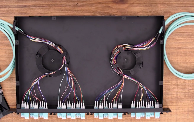
To terminate the cable, first slide the boot onto the fibre. Strip the fibre to at least about an inch and a half . Place a mark at 15.5 mm for ST and SC connectors or at 11.5 mm for LC connectors. Clean the stripped fibre with an alcohol wipe and remove any debris. Set the stripped fibre into the cleave and cleave it. Insert the cleaved fibre into the rear of the connector until the mark align with the back of the connector body. Slight the boot up and over the rear of the connector body. After the termination, transmission testing of assemblies need to be performed.
In the final fibre patch panel termination, first, open the front and rear door of the patch panel, and remove the covers. Remover the inter stain relief bracket. Second, use cable ties to put the cables on the bracket. The fibres should be put inside the clips on the tray to segregate the fibres from A and B slots. Put the patch panel into the panels clips. Take the excess fibre slack into the slack management clips. Make a bend in the fibre to maintain slight pressure on the connection.
Conclusion
The processes in the device connection and cable management are linking with each other that missing any or failure in any one will result in the imperfect system, or even the damage. If we own a fibre patch panel, we should make full use of its termination function. The products provided by FS,COM enable you to perfect your cabling system.
Patch panels are termination units, which are designed to provide a secure, organised chamber for housing connectors and splice units. Its main function is to terminate the fibre optic cable and provide connection access to the cable’s individual fibres. Patch panels can be categorised into different types based on a few different criteria. Last time, we have shed light on the copper and fibre patch panel and now let’s learn a different pair of it, namely wall mount patch panel and rack mount patch panel.
Wall Mount Patch Panel
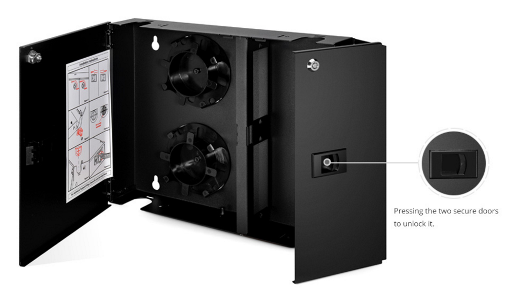
As the name suggests, wall mount patch panel is a patch panel fixed on the wall.The wall mount patch panels are designed to provide the essential interface between multiple fibre cables and optical equipment installed on the customer’s premises. The units offer networking and fibre distribution from the vault or wiring closet to the user’s terminal equipment.
This kind of patch panel consists of two separate compartments. As shown below, the left side is used for accommodating outside plant cables entering the building, pigtails and pigtail splices. Whereas, the right side is designed for internal cable assembly networking. And both sides have a door secured with a quarter turn latch.
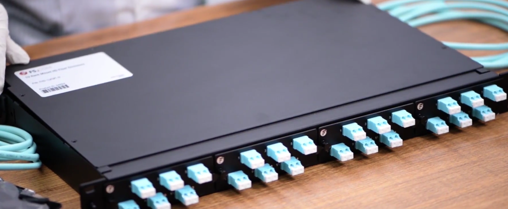
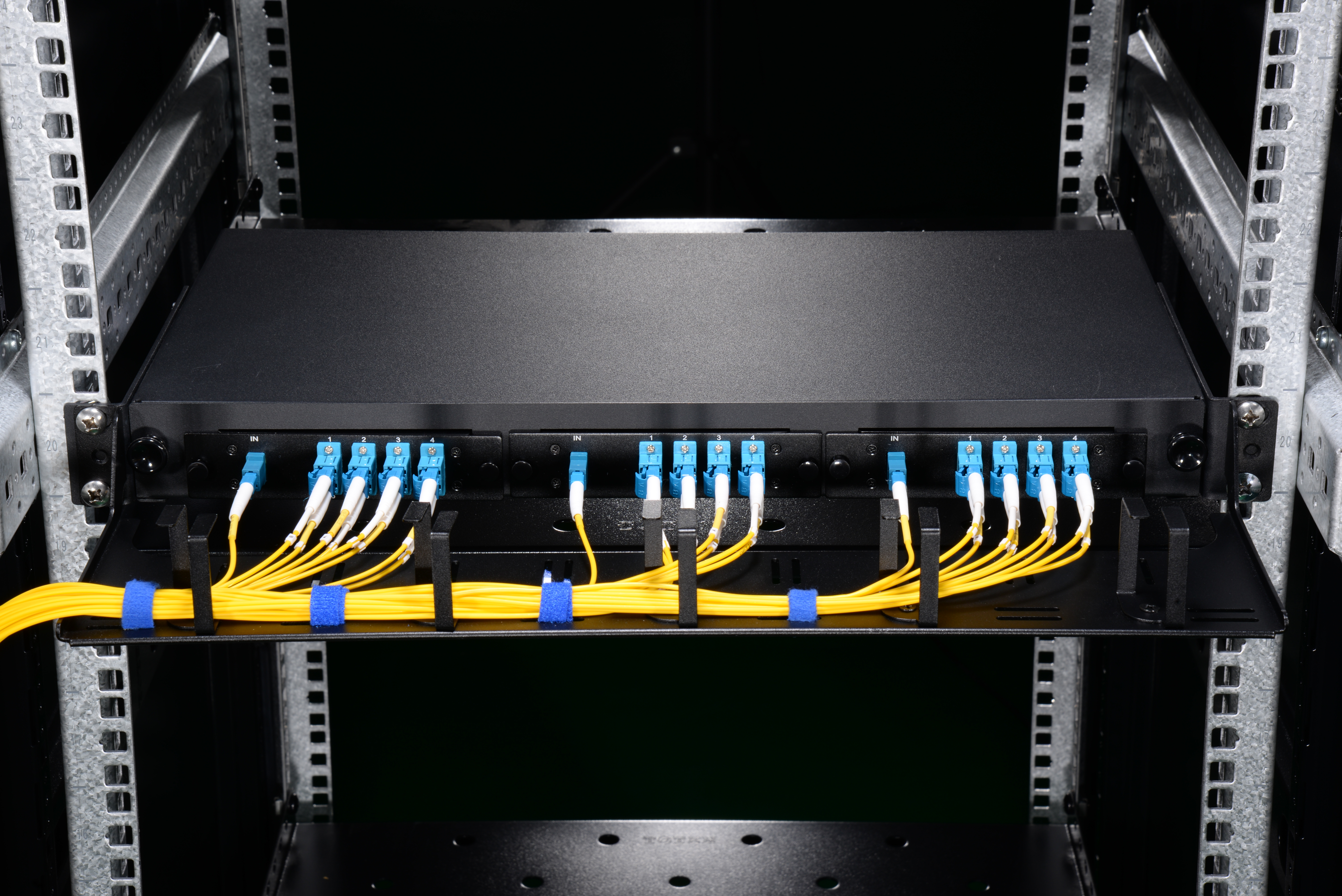
Rack Mount Patch Panel
The rack mount patch panel usually holds the fibres horizontally and looks like a drawer. Rack mount panel is designed in 1U, 2U, 4U sizes and can hold up to 288 or even more fibres. They can be mounted onto 19″ and 23″ standard relay racks. The rack mount enclosures include two kinds. One is the slide-out variety and the other incorporates a removable lid. As for the latter one, the tray can be pulled out and lowered to 10 degree working angle or even further 45 degree working angle to provide ease of access for maintenance or installation work.
Wall Mount VS Rack Mount Patch Panel
Installation
When installing wall mount patch panels, users need to leave at least 51mm additional space on each side to allow opening and removing the doors. Although it can be easily mounted to the wall by using the internal mounting holes, four screws are required when it is attached to a plywood wall, expansion inserts with wood screw for concrete walls and “molly bolts” for sheet rock. However, the installation of a rack patch panel just needs four screws without drilling the wall.
Space Occupation
Thinking from another perspective, the advantage of wall mount patch panels is that they allow you to optimise your work space by keeping equipment off floors and desks,which is superior to the rack mount patch panel.
Application
Both panels can be applied to Indore Premise Networks, Central offices (FTTx), Telecommunication Networks, Security Surveillance Applications, Process Automation & Control, Systems and Power Systems & Controls, while the rack mount patch panel has an advantage over the wall mount patch panel in that it can be applied to Data Centres.
Conclusion
To sum up, patch panels are available in rack mounted and wall mounted and are usually placed near terminating equipment (within patch cable reach). Both types can provide an easy cable management in that the panel ports can be labeled according to location, desktop number,etc. to help identify which cable from which location is getting terminated on which port on the patch panel, and changes can be made at the patch panel. The world-wide renown FS.COM can provide you the best quality rack mount and wall mount patch panel. Buyers are welcome to contact us.
Increasing bandwidth has always been the most important task of telecom engineers. Through decades of research and engineering effort, 40Gbps and 100Gbps solutions have been used for network applications. But 40G and 100G transceivers can’t support too much long distance (QSFP-40G-ER4 for 40 km, QSFP-100G-LR4 for 10 km). How to extend the 500Gbps link to thousands of kilometres in Metro network within limited budget?
Save Fibre Cost–500Gbps Over Single Fibre Cable
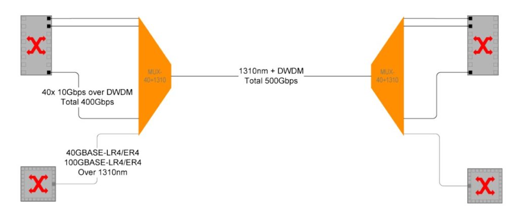
Fibre cable cost takes a certain percentage in the whole network budget. Point to point connection needs many cables, while WDM technology take well care of this issue. In a metro network, usually multiple 10Gbps signals are transmitted by the use of DWDM Mux/Demux over a single fibre cable, which can save lots of money on multiple fibre cables and cable management issues. Then how to save cost to transmit 500Gbps signals over single fibre cable?
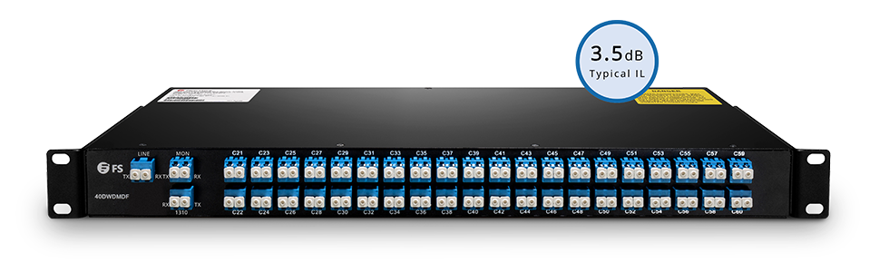
It sounds unbelievable. But we have the cost-effective solution. As we know, it will cost too much to replace all the current network system for upgrading to higher data rate. To save cost for increasing bandwidth, some producers add an extra port on DWDM Mux/Demux and that is 1310nm or 1550nm port. This port supports 1310nm or 1550nm transceiver. With such port, you can add 1G/10G/40G/100G to the existing DWDM network. For instance, we use 40-channel C21-C60 dual fibre DWDM Mux/Demux with 1310nm port and 1310nm band port for 1G/10G/40G/100G “grey” light. Plug 10G DWDM SFP+ transceivers into 40 channels, the overload is 400Gbps. Once plugging a 1310 40G QSFP+ LR4/ER4, then the total link reach up to 440G (400G + 40G). If install a 100G QSFP28 LR4 transceiver into 1310 port, the whole transport will be 500Gbps (400G + 100G). See this solution realize the goal of saving cost to run such huge network load over a single fibre.
Extend 500G Transmission Distance
Since 500G signals can be transmitted over a single fibre cable, we have another issue to be solved. 500G transmission distance is needed far more than few kilometres in real life, maybe thousand of kilometres. How to extend the transmission distance?
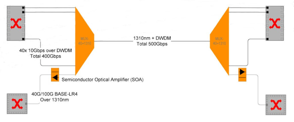
According to IEEE standard, LR4 and ER4 transceivers can support the reach of 10 km and 40 km in the in ideal conditions, not considering fibre loss or connector loss. To extend 500Gpbs transmission distance, we need SOA (Semiconductor Optical Amplifier) and EDFA (Erbium Doped Fibre Amplifier). Add an SOA to support 40G/100GBASE-LR4 transceiver (over 1310 nm). The SOA is used to amplify incoming (Rx) signal on the receiving side of the link. So that the distances can reach up to 60 km. In 10Gbps DWDM networks, the signal transmission distance can be extended to hundreds of kilometres by the use of and EDFA (Erbium Doped Fibre Amplifier).
Recommended DWDM Solutions for 500Gbps Metro Network
16dBm Output C-band 40 Channels 26dB Gain Booster EDFA
Summary
DWDM technology is very necessary to extend Metro Network reach. In this 500Gpbs Metro network, I have introduced very detailed cost-effective solutions. Remember all the indispensable DWDM equipment such as DWDM transceivers, DWDM Mux/Demux, EDFA, etc. For more information, please visit the site about FS.COM Long Haul DWDM Network Solution.
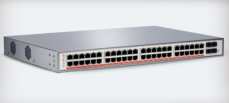
Currently IP cameras are widely used for video surveillance due to the high requirements for security. Typically, the IP cameras are with PoE functions, then PoE switch is needed for the connection. But some users feel confused about the PoE switch and don’t know how to choose a suitable PoE switch. This article is going to introduce you some guides on PoE switch selection.
PoE is short for power over Ethernet. With PoE technology, data and power can be transmitted over a single Cat5e cable. A PoE switch is a device that contains multiple Ethernet ports to provide power and network communications to IP cameras. PoE switch is an economical and reliable solution for small business networks to deploy wireless access points and IP surveillance cameras.
Considerations for PoE Switch Selection
Numbers of Ports
The most important is to check whether the numbers of ports on PoE switch are enough to connect all your devices. Fiberstore offers PoE switches including 8 ports, 24 ports, and 48 ports. PoE ports are flexible to connect with Cat5e cable without additional settings. All of our PoE switches have 2 Gigabit uplink SFP ports or 4 SFP+ ports. Uplink ports allow long distance data transmission between switches. With these ports, you can easily expand your networks. (Check news about PoE switch from FS.COM: Build and Expand Your Network with FS.COM New Introduced PoE Switches) So if you need to link multiple switches, you need to select switches with enough Gigabit ports.
Power Supplies for Powered Device
PoE switch applies two standards: IEEE802.3af and 802.3at. Each one can offer power for IP cameras. Due to the different standards, the output power of PoE switch is also different. IEEE802.3af can provide 15.4watts DC power on each port. As some power dissipates in the cable, only 12.95watts power at most can be supplied to powered devices. This standard is enough to power VoIP phones, wireless access points and some cameras over standard Ethernet cabling. While, IEEE802.3at is updated PoE standard known as PoE+. It can provide up to 25.5watts power available for powered device which is nearly twice as many as that 802.3af supplies. The updated standard can support more devices with high-power functionality such as door controllers, cameras with zoom capacity, or wireless access points supporting 802.11n.
Total Power
PoE switch has a total power. As described before, under IEEE802.3af standard, each port on the PoE switch can get 15.4watts power. Thus, the total power of a 24-port switch must reach 370watts so that it can make sure each port get sufficient power. And make sure there is additional power beyond that required for PoE for its switching functions. As to the IEE802.3at standard, each port supports 30watts. Under this condition, the PoE switch with total power of 370watts can only provide power supply to 12 ports.
Cable Requirements
The DC power of IEEE 802.3af standard is 15.4watts. It can support 10BASE-T and 100BASE-T. Two of four twisted pairs of Cat3 cable or higher can support the power and data transmission. The PoE+ standard delivers power up to 30watts and supports 1000BASE-T. Cat5e or Cat6 cable is able to support the power transmission. Connecting PoE switch to the router or cameras with Cat5e or Cat6 cable, the maximum transmission length is up to 100 meters.
When buying Ethernet cables, find a reliable vendor who provides standard network cable meeting the strict requirement. PoE power supply must use oxygen-free copper material—standard network cable. Non-standard cable utilizes other materials such as copper clad steel, copper clad aluminum, copper coated iron, etc. These cables are not suitable for PoE power supply because of the big resistance.
Conclusion
PoE switch is a cost-effective solution to increase the reliability and security of networks by providing centralized backup power to all connected IP surveillance devices. Before purchasing PoE switches, try to know as more details about the switch specifications as possible and also your own needs. To get good quality PoE switches, please come to FS.COM.
Nowadays, wireless LAN (local area network) becomes an independent part in our daily life. As waiting for your dishes in a restaurant, you may take out your phone and connect the Wi-Fi. I guess most of you have a wireless LAN. But if you have no or intend to upgrade your network, you’d better read this article on how to choose a wireless access point (AP).
Wireless AP Standards: 802.11n and 802.11ac
There are two newest IEEE wirelesss network standards including 802.11n (debuting in 2009) and 802.11ac (in 2014). The earlier 802.11n standard can support up to 540 Mbps, while the optimized 802.11ac products can provide the speed up to 1.3Gbps. 802.11ac is faster and more scalable than 802.11n. Except the improved speed, 802.11ac access points also optimize in the areas of range and reliability. Considering these factors, many enterprises may use 802.11ac technology.
However, though 802.11ac is better than 802.11n, it doesn’t mean it suits for everyone. First, 802.11ac needs big room for super wide channels. Second, you need to buy devices matching 802.11ac technology. At last, those devices should be close (20 or 30 feet) to the access point.
Dual Band Wireless AP or Single Band Wireless AP
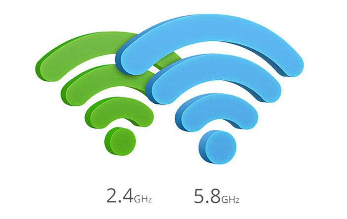
Before discussing about dual band and single band, we need to know 2.4 GHz and 5 GHz. 2.4 GHz is a lower frequency than 5 GHz. It can penetrate most obstructions better. The signal can reach further. Wireless access point is one of the devices which use 2.4 GHz. While 5 GHz has a higher frequency, signals can’t penetrate solid obstructions like walls as easily as 2.4 GHz. 5 GHz provides us with more usable channels.
In the past, some 802.11n wireless AP is single band and can only support 2.4 GHz. It fails to meet the demands for 5GHz devices. Thus, the trend urges the appearance of new dual-band access point. Dual-band means that the access point can transmit and receive in two separate bands. Dual-band access points can support 2.4 GHz speeds and leverage wide channels, high data rates for connecting 5GHz devices. When you buy access points, make sure the one you choose can support both 2.4 GHz and 5 GHz.
Spatial Streams of Wireless AP
The number of spatial streams is one of the influencing factors on wireless speed. 802.11n stopped at four spatial streams, but 802.11ac goes all the way to eight. 802.11n introduced MIMO (more multiple input, multiple output). MIMO means that we can get multiple radio chains and antennas to transmit and receive. The more radio chains, the faster the wireless network speed. With 802.11n, a device can transmit multiple spatial streams at once, but only directed to a single address. It means only one user can get data at a time. That’s called single-user MIMO (SU-MIMO). While with 802.11ac, multi users can get data at the same time. And that’s called multiuser MIMO (MU-MIMO). As you can see, the more spatial streams, the better.
Get Wireless APs From Fiberstore
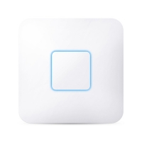
We provide three types of wireless APs which can be applied to enterprises, schools, hotels, etc. Our wireless APs contain the good features of easy plug & play installation and intuitive management, which is beneficial for reducing the need for dedicated IT personnel resources. And the unique watchdog technology makes AP work more stable and ensure the wireless network operate properly. Repeater mode makes wireless coverage more flexible. Both 802.11n and 802.11ac APs (as shown in the table below) can be found in Fiberstore.
Image
2.4GHz Speed
5.8GHz Speed
CPU
Antenna Gain
AP-S300
300 Mbps
No
533 MHz
2x3dBi
AP-D1200
300 Mbps
867 Mbps
650 MHz
4x3dBi
AP-D1750
450 Mbps
1300 Mbps
720 MHz
6x3dBi
Conclusion
This article is to give you some advice on how to choose a wireless access point. Well, when you decide to buy one, remember the tips mentioned above including standards, dual band or single band, spatial streams. The most suitable is the best. A reliable vendor is also important. Hope this article can help you find your desirable wireless AP.
Passive optical network (PON) has been widely applied in the construction of FTTH (fibre to the home). With PON architecture, network service providers can send the signal to multiple users through a single optical fibre, which can help them save great costs. To build the PON architecture, optical fibre splitter is necessary.
What Is Fibre Splitter?
The fibre splitter is a passive component specially designed for PON networks. Fibre splitter is generally a two-way passive equipment with one or two input ports and several output ports (from 2 to 64). Fibre splitter is used to split the optical signal into several outputs by a certain ratio. If the ratio of a splitter is 1×8 , then the signal will be divided into 8 fibre optic lights by equal ratio and each beam is 1/8 of the original source. The splitter can be designed for a specific wavelength, or works with wavelengths (from 1260 nm to 1620 nm) commonly used in optical transmission. Since fibre splitter is a passive device, it can provide high reliability for FTTH network. Based on the production principle, fibre splitters include Planar Lightwave Circuit (PLC) and Fused Bionic Taper (FBT).
PLC splitters are produced by planar technology. PLC splitters use silica optical waveguide technology to distribute optical signals from central office to multiple premise locations. The output ports of PLC splitters can be at most 64. This type of splitters is mainly used for network with more users.
The Structure of PLC splitters
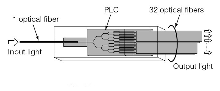
Internal Structure
The following figure shows a PLC splitter. The optical fibre is splitted into 32 outputs. PLC chip is made of silica glass embedded with optical waveguide. The waveguide has three branches of optical channels. When the light guided through the channels, it is equally divided into multiple lights (up to 64) and transmitted via output ports.
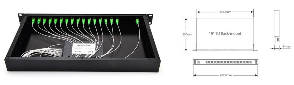
Outside Configuration
Bare splitter is the basic component of PLC fibre splitter. For better protection of the fragile fibre and optimised use, PLC splitters are often equipped with loose tube, connector and covering box. PLC splitters are made in several different configurations, including ABS, LGX box, Mini Plug-in type, Tray type, 1U Rack mount, etc. For example, 1RU rack mount PLC splitter (as shown in the figure below) is designed for high density fibre optical distribution networks. It can provide super optical performance and fast installation. This splitter is preassembled and fibres are terminated with SC connectors. It’s ready for immediate installation.
FBT splitters are made by connecting the optical fibres at high temperature and pressure. When the fibre coats are melted and connected, fibre cores get close to each other. Then two or more optical fibres are bound together and put on a fused taper fibre device. Fibres are drawn out according to the output ratio from one single fibre as the input. FBT splitters are mostly used for passive networks where the split configuration is smaller.
PLC Splitters From FS.COM
Fiberstore offers a wide range of PLC splitters that can be configured with 1xN and 2xN. Our splitters are designed for different applications, configurations including LGX, ABS box with pigtail, bare, blockless, rack mount package and so on.
Port Configuration
Package Style
Fibre Diameter
(Input/output)
Connector (Input/output)
Pigtail Length
1×2
Steel tube, bare fibre
250μm
None
1.5m
1×4
Mini module
900μm
SC APC/UPC
2.0m
1×8
Pigtailed ABS box
2.00mm
LC APC/UPC
3.0m
1×16
Mini plugged-in
3.0mm
FC APC/UPC
Customised
1×32
LGX
ST APC/UPC
1×64
Splice Tray Type
Customised
2×16
Rack mount
Conclusion
Fibre splitter is an economical solution for PON architecture deployment in FTTH network. It can offer high performance and reliability against the harsh environment conditions. Besides, the small sized splitter is easy for installation and flexible for future network reconfiguration. Therefore, it’s a wise choice to use fibre splitter for building FTTH network.
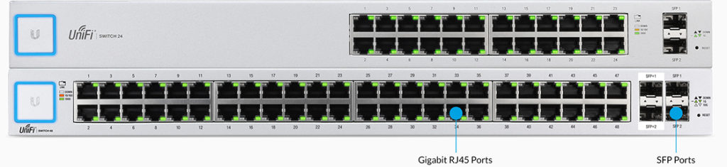
UniFi switches has been introduced into the market by Ubiquiti (The other kind is Ubiquiti EdgeSwitch). The UniFi switch provides fibre connectivity options for easy expansion of your networks. This article will introduce the main features of UniFi switches, supportable SFP and SFP+, and easy tips for building network with UniFi switch.
Introduction to UniFi Switches
UniFi switch delivers high performance to satisfy your growing network. The Ubiquiti UniFi switches include US-24 and US-48. US-24 can support data rates up to 26 Gbps while US-48 can support the network speed up to 70 Gbps of non-blocking throughput. Main features of these two switches are described as below.
Features of US-24 switch:
24 Gigabit RJ45 ports
2 SFP ports
52Gbps switching capacity
250W max. power consumption
Rack mountable
Features of US-48 switch:
48 Gigabit RJ45 ports
2 SFP+ ports
2 SFP ports
140Gbps switching capacity
56W max. power consumption
Rack mountable
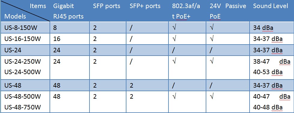
Except the above two switches, there are some other kinds containing US-8-150 (with 8 Gigabit RJ45 ports and 2 SFP ports) and US-16-150W (with 16 Gigabit RJ45 ports and 2 SFP ports). Both switches are available with different models. You can find the details about these models from the following table.
Compatible SFP and SFP+ for UniFi Switches
If you are wondering which SFP and SFP+ are suitable for UniFi switch, you can get the answer now. You have two choices for getting suitable transceiver modules. Ubiquiti produces single-mode and multimode SFP and SFP+ modules for UniFi switches. UF-MM-1G and UF-MM-1G-S are designed for SFP ports. Three modules such as UF-SM-10G, UF-SM-10G-S, and UF-MM-10G are appropriate for SFP+ ports.
Of course, transceiver modules for UniFi switch are not limited to these original SFP/SFP+. A wide range of third-party transceivers can also work with UniFi switch. The following table will show you some compatible SFPs for Unifi switch from FS.COM.
1m Cisco SFP-H10GB-ACU1M Compatible 10G SFP+ Active Direct Attach Copper Cable
Building Connection With Unifi Switches
To build the UniFi network, you have to prepare installation screwdriver, at least 1U rack, UTP Cat 5 (or above) for indoor applications and STP Cat5 (or above) for outdoor applications. It’s quite easy.
First, install the UniFi switch on the rack with four mounting screws. Then plug one end of the power cord into the power port of the UniFi switch and the other end into the power outlet.
Second, connect Ethernet cables from your devices to RJ45 ports of UniFi switch.
Third, plug an SFP transceiver into the SFP port if you need to use it. After that, connect the SFP module with a fibre patch lead.
Conclusion
UniFi switches are very commonly used for network connection. To build the network, you don’t need to spend much time on searching cables or modules from the internet. FS.COM offers fibre patch leads and Ethernet cables for your connection. We also provide some compatible SFPs and SFP+s definitely compatible for UniFi switch. Every module has been strictly tested to make sure high quality. Just come to our site and you must get 100% compatible SFP or SFP+s for your UniFi switch.