Monthly Archives: January 2016

MPO/MTP Polarity in Data Centres

Today, data centres are being built to support 40G/100G transmissions. MPO/MTP interface patch cables are created to support 40G/100G data rates. Different from traditional 2–fibre configurations, with one send and one receive, 40G & 100G Ethernet implementations over MPO/MTP fibres use multiple parallel 10G connections that are aggregated. 40G uses four 10G fibres to send and four 10G fibres to receive, while 100G uses ten 10G fibres in each direction. To ensure the systems work well, it’s important to better know MPO/MTP polarity to keep the right fibre connections.

Understanding the Polarity

Maintaining the correct polarity across a fibre network ensures that a transmit signal from any type of active equipment will be directed to the receive port of a second piece of active equipment–and vice versa. The polarity means that once the signal is received, the electronics will sort out and organize the stream of data. Transmits will be connected to receives. Every send needs its own receive just like the ball players with pitchers & catchers. For 10G transmission, Pitcher 1 needs to throw to Catcher 1, Pitcher 2 to Catcher 2 and so on. For 40/100G, any pitcher can throw to any catcher. But if you’ve got two catchers looking at each other – the play can’t go on.

Three Connecting Methods

According to the TIA 568 standard, there are three methods for configuring systems to make proper connections, Methods A, B & C for multi‐fibre arrays using MPO/MTP connectors. Each of these methods handle the transition from a transmit position to a receive position in a slightly different manner, and each employs a backbone cable that is constructed in a specific manner.

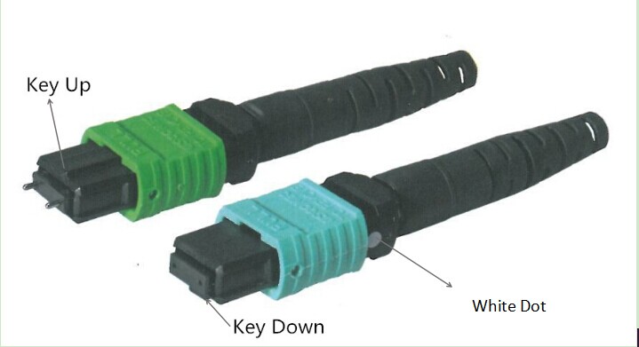
Before looking at each method in detail, it’s necessary to know MPO/MTP connectors. The following will introduce MTP connector. Each MTP connector has a key on one side of the connector body. When the key sits on top, it means the key up position. In this orientation, each of the fibre holes in the connector is numbered in sequence from left to right. We will refer to these connector holes as positions, or P1, P2, etc. There is also a white dot marked on the right connector body to designate the position P1 of the connector when it’s plugged in.

MTP-connector

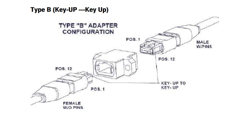
MTP adaptor is designed to hold the two MTPs. As each MTP has a key, there are two types of MTP adaptors (as shown in the following figure):

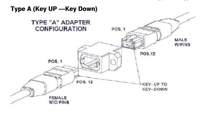
Type A—key-up to key-down. Here the key is up on one side and down on the other. The two connectors are connected turned 180° in relation to each other;

Type A

Type B—key-up to key-up. Here both keys are up. The two connectors are connected while in the same position in relation to each other.

Type B

  • Method A—The transmit‐receive flip must happen in the patch cords, and the trunk cable is a straight through transmission, with the key up on one end, and the key down on the opposite end. This means that the fibre at Position 1 (P1) of the connector on the left will arrive at P1 of other connector.
  • Method B—The keys are in an up position at both ends of the trunk cable, but the fibre at P1 in one connector end is at P12 at the opposite end, and the fibre at P12 at the originating end is at position 1 at the opposing end. The fibre positions of Type B cable are reversed at each end.
  • Method C—This method uses key up to key down adapters to connect array connector. Each adjacent pair of fibres at one end are flipped at the other end.
40G/100G Transmission Connectivity

40G needs an MPO 12 fibre connector. Only 8 fibres of the 12 are applied with other 4 remaining dark. Four positions are used to transmit, the other four positions are used to receive. 100G requires the use of an MPO 24 fibre connector. The 100G is split into 10 x 10G channels, 10 for transmitting and 10 for receiving.

To upgrade to 40G/100G data transmissions, network designers should better understand well the MPO/MTP polarity. Select the right types of MPO cables, MPO connectors, MPO cassette and patch cables, the proper solution for data centres would be achieved with high density and flexibility and reliability.

How Much Do You Know Fibre Optic Testing?

For every fibre optic cable plant, you need to test for continuity and polarity, end-to-end insertion loss, etc. If there were a problem, it must be fixed to keep the fibre optic cable plant working properly and ensure the communications equipment operate well.

fiber-optic-testing

Testing Tools

Fibre optic cable testing needs special tools and instruments. And they must be appropriate for the components or cable plants being tested. The following five kinds of fibre testing tools are needed for the testing work.

OLTS—Optical loss test set (OLTS) with optical ratings matching the specifications of the Finstalled system (fibre type and transmitter wavelength and type) and proper connector adapters. Power metre and source are also needed for testing transmitter and receiver power for the system testing.
Reference test cable—This cable should be with proper sized fibre and connectors and compatible mating adapters of known good quality. And the connector loss is less than 0.5 dB.
VFL—Visual fibre tracer or visual fault locator (VFL)
Microscope—Connector inspection microscope with magnification of 100-200X, video microscopes recommended.
Cleaning Materials—Cleaning materials intended specifically for the cleaning of fibre optic connectors, such as dry cleaning kits or lint free cleaning wipes and pure alcohol.

Notes Before Testing
Cleaning Issue

Before testing, it’s very important to keep connector clean so that there is no dirt present on the end face of the connector ferrule as the dirt will cause high loss and reflectance. For example, the dust caps which is used to keep connectors clean usually contain dust. So it may leave residue or cause harm to the connectors to use cleaning tools with dirt.

Eye Protection

Connector inspection microscopes focus all the light into the eye and can increase the danger. Some DWDM and CATV systems have very high power and they could be harmful. Though fibre optic testing sources are too low in power to cause eye damage, it’s still suggested to check connectors with a power metre before looking it. As most fibre optic sources are at infrared wavelengths that are invisible to the eye, making them more dangerous. So better protect your eyes from these potential harms.

Loss Budget

Before testing, you should clearly know the loss budget as reference loss values for the cable plant to be tested. Here are some guidelines:

    • For connectors, 0.3-0.5 dB loss; for adhesive/polish connectors, 0.75 dB loss; for prepolished/splice connectors (0.75 max from TIA-568)
    • For single-mode fibre, 0.5 dB/km for 1300 nm, 0.4 dB/km for 1550 nm. It means a loss of 0.1 dB per 600 feet for 1300 nm, 0.1 dB per 750 feet for 1550 nm.
    • For each splice, 0.2 dB
    • For multimode fibre, the loss is about 3 dB/km for 850 nm, 1 dB/km for 1300 nm. It means a loss of 0.1 dB per 100 feet for 850 nm, 0.1 dB per 300 feet for 1300 nm.

So for the loss of a cable plant will calculated as (0.5 dB X # connectors) + (0.2 dB x # splices) + fibre loss on the total length of cable.

Fibre Optic Loss Testing

Before installation, it’s necessary to inspect all cables as received on the reel for continuity using a visual tracer or fault locator. An OTDR is needed to test if cables are damaged during the shipment. Any cable showing damage should not be installed.

After installation, all cables should be tested for insertion loss using a metre of OLTS according to standards OFSTP-14 for multimode fibre and OFSTP-7 for single-mode fibre. Usually cables are tested individually (connector to connector for each terminated section of cable and then a complete concatenated cable plant is tested “end-to-end”, excluding the patch cords that will be used to connect the communications equipment which are tested separately. Insertion loss testing should be done at the wavelengths of 850/1300 nm with LEDs for multimode fibre, 1310/1550 nm with lasers for single-mode fibre, 1490 for FTTH. Keep the data on insertion loss for future comparisons if problems arise or restoration becomes necessary. Long cables with splices may be tested with an OTDR to confirm splice quality and detect any problems caused during installation, but insertion loss testing with an OLTS (light source and power metre) is still required to confirm end-to-end loss.

Testing Results and Methods

If the cable plant loss is tested within the loss budget, the communication link should work properly.

If the loss is higher than the loss budget, first you need to test in the opposite direction using the single-ended method. Since this method can only test the connector on one end, you can isolate a bad connector. If the tested losses are the same on both directions, you need to test each segment separately to isolate the bad segment or use an OTDR if it is long enough.

If there is no light through the cable and only darkness when tested with your visual tracer, there must be very high loss. Then you need to cut the connector on one end (maybe the wrong one) by your decision.

Originally published at http://www.articlesfactory.com/articles/communication/how-much-do-you-know-fibr-optic-testing.html

What Should You Know Before Using an OTDR?

OTDR, the optical time domain reflectometer, is the most important investigation tool for optical fibres. It’s applied in the measurement of fibre loss, connector loss and for the determination of the exact place and the value of cable discontinuities. It’s the only device which can verify inline splices on concatenated fibre optic cables and locating faults.

To know how to use OTDR for the fibre investigations, first you should know the structure and working principle of OTDR equipment. When a short light pulse transmits into the fibre under test, the time of the incidence and the amplitude of the reflected pulses are measured. The commonly used pulse width ranges from nanosecs to microsecs, the power of the pulse can exceed 10 mW. The repetition frequency depends on the fibre length, typically is between 1 and 20 kHz, naturally it is smaller for longer fibres. The division by 2 at the inputs of oscilloscope is needed since both the vertical (loss) and the horizontal (length) scales correspond to the one-way length.

jdsu-mts-4000-otdr

Besides, to use an OTDR successfully, you should also know how to operate the instrument. The following is about the experiences collected from some experienced people who use OTDRs during installation and for maintaining telecommunication networks.

Keep Connectors Clean

Before use OTDR, first, you should watch out if the connectors are clean. If it’s dirty, then clean it. Otherwise, it will make measurements unreliable, noisy or even impossible. What’s worse, it may damage the OTDR.

Check the Connector or the Patch Cord

Check whether the patch cord, the module, and the fibre under test are single-mode or multimode. To test the patch cord, activate the laser in the CW (Coarse Wavelength) mode and measure the power at the end of the patch cord with a power meter. This should be between 0 and – 4 dBm for most single-mode modules and wavelengths.

Set the Range

The range is the distance over the cable which the OTDR will measure. The range should be longer than the cable you are testing. For example, if your link is 56.3 km long, choose 60 km. For distances greater than approximately 15 km, make your first measurement in longhaul mode, otherwise use shorthaul.

Determine the Wavelength

Usually single-mode is set for 1310 nm or 1550 nm, and multimode is set for 850 nm or 1300 nm.

Averages of Noisy Traces

If the trace is very noisy, increase the number of averages. Usually 16-64 averages are adequate. To improve the signal to noise ration of the trace, the OTDR can average multiple measurements, but averaging takes time. So try to average over a longer time.

Realtime Mode

In this mode, you can modify parameters only if you stop a measurement explicitly. So it avoids you to erase a trace averaged over a long time by accident. You use realtime mode to check your connection, the quality of splices, and whether a fibre is connected. Start in automatic mode, then switch to realtime mode and select the most suitable parameters.

Adjust the Refractive Index

If you know the exact physical length of the fibre under test, you can measure the refractive index. Start with the refractive index 1.5000. Place a marker at the end of the fibre. Then select the refractive index function and adjust it until the displayed marker position is equal to the known fibre length. Then, the effective refractive index will be displayed.

Macrobending Loss

Single-mode fibres (1550 nm) are very sensitive to macrobending such as a tight bend or local pressure on the cable. It doesn’t always happen at this wavelength of 1310 nm. So characterise your link at both wavelengths.

OTDRs are invaluable test instruments. Maybe a small mistake will cause serious damage to this equipment. So before use it, you should better know it as detailed as possible to avoid any loss because of innocence and make full use of it in optical fibre events.

Related article:
How to Choose a Right OTDR?
OTDR Selection Guide

How to Choose a Right OTDR?

An optical time-domain reflectometre (OTDR) is an optoelectronic instrument used to measure fibre loss, the loss and reflectance of fibre splices, and to locate loss irregularities within the fibre. Now there are many types of OTDRs providing different test and measurement needs including very simple fault finders and advanced OTDRs for link certification. Then, how to choose the right one?

aq1200-mft-otdr

First, you should evaluate your needs. Installing or maintaining fibre? For simple maintenance, a simple or low cost OTDR is good. It’s easy to use, requires the lowest possible investment and some even provides total link loss and optical return loss values. For not very complex installation, you should choose a mini OTDR based on the following key parametres for your specific environment.

Dynamic Range

This specification determines the total optical loss that the OTDR can analyze; i.e., the overall length of a fibre link that can be measured by the unit. The higher the dynamic range, the longer the distance the OTDR can analyze. Insufficient dynamic range will influence the ability to measure the complete link length and affect the accuracy of the link loss, attenuation and far-end connector losses. It’s good to choose an OTDR whose dynamic range is 5 to 8 dB higher than the maximum loss you will encounter.

Dead Zones

Dead zones originate from reflective events (connectors, mechanical splices, etc.) along the link, and they affect the OTDR’s ability to accurately measure attenuation on shorter links and differentiate closely spaced events, such as connectors in patch panels, etc. There are two types of dead zones to specify OTDR performance:

Attenuation dead zone refers to the minimum distance required, after a reflective event, for the OTDR to measure a reflective or non-reflective event loss. Try to choose OTDR with the shortest possible attenuation dead zone to measure short links and to characterize or find faults in patchcords and leads. Industry standard values range from 3 m to 10 m for this specification.

Event dead zone is the distance after a reflective event starts until another reflection can be detected. If a reflective event is within the event dead zone of the preceding event. Industry standard values range from 1 m to 5 m for this specification. The event dead zone specification is always smaller than the attenuation dead zone specification.

Sampling Resolution

Sampling resolution refers to the minimum distance between two consecutive sampling points acquired by the instrument. This is a quite important parametre as it defines the ultimate distance accuracy and fault-finding capability of the OTDR.

Pass/Fail Thresholds

This parametre is also important because lots of time can be saved in the analysis of OTDR traces if you set Pass/Fail thresholds for parametres of interest (e.g., such as splice loss or connector reflection). These thresholds highlight parametres that have exceeded a Warning or Fail limit set and, when used in conjunction with reporting software, it can rapidly provide re-work sheets for installation/commissioning engineers.

Report Generation

If an OTDR has specialized post-processing software allowing fast and easy generation of OTDR reports, it can save up to 90% post-processing time. These can also include bidirectional analyses of OTDR traces and summary reports for high-fibre-count cables.

To choose a right OTDR for your test application, you should better consider the above factors. FS offers YOKOGAWA AQ1200A, EXFO AXS-110-23B-04B OTDR, etc,. with great accuracy, measurement range and instrument resolution. There must be one suitable for you and helpful to maximize your return on investment.

Originally published at http://www.articlesfactory.com/articles/communication/how-to-choose-a-right-otdr.html

Related article: What Should You Know Before Using an OTDR?