Correctly splicing and terminating fibre optic cable requires special tools and methods. Training is essential and there are many excellent causes of training available. Do not mix your electrical tools with your fibre tools. Use the right tools to do the job! Being experienced in fibre work will end up increasingly necessary because the importance of data transmission speeds, fibre towards the home and fibre to the premise deployments still increase.
Many factors set fibre installations apart from traditional electrical projects. Fibre optic glass is very fragile; it’s nominal outside diameter is 125 micron. The slightest scratch, mark or perhaps speck of dirt will affect the transmission of light, degrading the signal. Safety factors are important because you will work with glass that can sliver to your skin without being seen through the human eye. Transmission grade lasers are extremely dangerous, and require that protective eyewear is a must. This industry has primarily been coping with voice and data grade circuits that may tolerate some interruption or slow down of signal. The person speaking would repeat themselves, or even the data would retransmit. Today we are dealing with IPTV signals and customers who’ll not tolerate pixelization, or momentary locking from the picture. All the situations mentioned are reason for the client to look for another carrier. Each situation might have been avoided if proper attention was handed towards the techniques used when preparing, installing, and maintaining fibre optic cables.
Jacket Strippers are utilized to remove the 1.6 – 3.0mm PVC outer jacket on simplex and duplex fibre cables. Fibre Cutters will cut and trim the kevlar strength member directly underneath the jacket and Buffer Strippers will take away the acrylate (buffer) coating from the bare glass. A protective plastic coating is used to the bare fibre after the drawing process, but just before spooling. The most typical coating is really a UV-cured acrylate, that is applied in two layers, producing a nominal outside diameter of 250 micron for that coated fibre. The coating is highly engineered, providing protection against physical damage caused by environmental elements, such as humidity and temperature extremes, contact with chemicals, reason for stress… etc. whilst minimizing optical loss. Without it, the manufacturer wouldn’t be in a position to spool the fibre without breaking it. The 250 micron-coated fibre may be the building block for a lot of common fibre optic cable constructions. It is usually used as is, particularly when additional mechanical or environmental protection is not needed, for example inside of optical devices or splice closures. For additional physical protection and easy handling, a secondary coating of polyvinyl chloride (PVC) or Hytrel (a thermoplastic elastomer that has desirable characteristics to be used as a secondary buffer) is extruded within the 250 micron-coated fibre, increasing the outside diameter as much as 900 micron. This kind of construction is called ‘tight buffered fibre’. Tight Buffered may be single or multi fibre and are observed in Premise Networks and indoor applications. Multi-fibre, tight-buffered cables often can be used for intra-building, risers, general building and plenum applications.
‘Loose tube fibre’ usually includes a bundle of fibres enclosed inside a thermoplastic tube referred to as a buffer tube, which has an inner diameter that is slightly larger than the diameter of the fibre. Loose tube fibre has a space for the fibres to grow. In a few climate conditions, a fibre may expand after which shrink over and over again or it may be exposed to water. Fibre Cables will sometimes have ‘gel’ within this cavity (or space) yet others that are labeled ‘dry block’. You will find many loose tube fibres in Outside Plant Environments. The modular design of loose-tube cables typically stands up to 12 fibres per buffer tube with a maximum per cable fibre count in excess of 200 fibres. Loose-tube cables can be all-dielectric or optionally armored. The armoring is used to protect the cable from rodents such as squirrels or beavers, or from protruding rocks in a buried environment. The modular buffer-tube design also permits easy drop-off of categories of fibres at intermediate points, without disturbing other protected buffer tubes being routed to other locations. The loose-tube design also helps in the identification and administration of fibres within the system. When protective gel is present, a gel-cleaner such as D-Gel will be needed. Each fibre will be cleaned with the gel cleaner and 99% alcohol. Clean room wipers (Kim Wipes) are a good choice to use with the soap. The fibres inside a loose tube gel filled cable will often have a 250 micron coating so that they tend to be more fragile than the usual tight-buffered fibre. Standard industry colour-coding can also be accustomed to identify the buffers along with the fibres in the buffers.
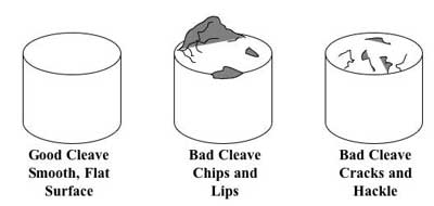
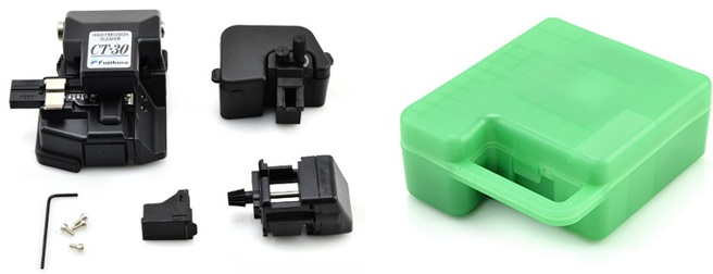
A ‘Rotary Tool’ or ‘Cable Slitter‘ can be used to slit a diamond ring around and thru the outer jacketing of ‘loose tube fibre’. Once you expose the durable inner buffer tube, you can use a ‘Universal Fibre Access Tool’ that is designed for single central buffer tube entry. Utilized on the same principle because the Mid Span Access Tool, (which allows access to the multicoloured buffer coated tight buffered fibres) dual blades will slit the tube lengthwise, exposing the buffer coated fibres. Fibre handling tools such as a spatula or perhaps a pick can help the installer to access the fibre in need of testing or repair. Once the damaged fibre is exposed a hand- stripping tool will be used to take away the 250 micron coating in order to work with the bare fibre. The next step is going to be cleaning the fibre end and preparing it to be cleaved. A great cleave is among the most important factors of manufacturing a low loss on the splice or a termination. A Fibre Optic Cleaver is really a multipurpose tool that measures distance in the end of the buffer coating enough where it will likely be joined also it precisely cuts the glass. Always remember to utilize a fibre trash-can for that scraps of glass cleaved from the fibre cable.
When performing fusion splicing you may need a Fusion Splicer, fusion splice protection sleeves, and isopropyl alcohol and stripping tools. If you are using a mechanical splice, you will need stripping tools, mechanical splices, isopropyl alcohol and a mechanical splice assembly tool. When hand terminating a fibre you will need 99% isopropyl alcohol, epoxy/adhesive, a syringe and needle, polishing (lapping) film, a polishing pad, a polishing puck, a crimp tool, stripping tools, fibre optic connectors (or splice on connectors) and piano wire.
Whenever a termination is complete you have to inspect the finish face of the connector having a Fibre Optic Inspection Microscope. Ensuring light is getting most likely through the splice or even the connection, a visible Fault Locator may be used. This piece of equipment will shoot a visible laser down the fibre cable so you can tell there are no breaks or faulty splices. If the laser light stops on the fibre somewhere, there’s most likely a break in the glass at that point. If you find more than a dull light showing in the connector point, the termination was not successful. The light should also pass through the fusion splice, if it does not, stop and re- splice or re-terminate.