Category Archives: Fiber Cabling

Interconnect and Cross Connect in Data Center

As massive amounts of data are transferred and stored across the globe, many organizations are placing greater emphasis on network performance to provide great customer service and build a fast and reliable network for their employees. Improving network connectivity in data centers is one of the most basic and critical ways to optimize network and hybrid architecture. When it comes to the connection between the horizontal cabling and active equipment such as switches, there are two basic configurations that are interconnect and cross connect.

Interconnect and Cross Connect Basics

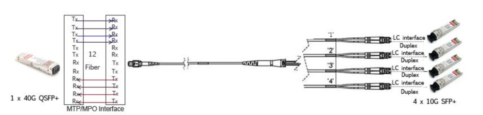
Interconnect in data center is to use a patch panel on the active equipment to distribute links from device to other devices in the data center, commonly known as the distribution panel. In an interconnect system, patching is done directly between the active equipment and the distribution patch panel. More specifically, outlets are terminated to a patch panel, and the patch panel is then patched directly to a switch, as shown in the figure below.

Interconnect
Interconnect

A cross connect in data center is the use of additional patch panels to mirror the ports of the equipment being connected, essentially creating a separate patching zone that provides connection between different equipment by patch cords. In a cross-connect system, the switch ports are replicated on the additional patch panel, also called equipment patch panel, and patching is carried out between the equipment patch panel and the distribution patch panel. Basically, there are two types of cross-connects, which are three-connector cross-connect and four-connector cross connect.

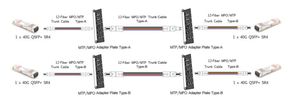
The structure of a three-connector cross connect is similar to interconnect mentioned above, just adding a cross-connecting process at the switch end, as shown below.

Three-Connector Cross Connect

Four-connector cross connect usually requires a patch field which is usually an individual cabinet. In this case, two copper trunk cables are working as permanent cables, making the cabling system easier to manage.

Four-Connector Cross Connect

Interconnect Vs Cross Connect: How to Choose?

Currently, most cabling systems use interconnect design. But some people indicate the cross connect is preferred as it increases the reliability of the system. Choosing the right cabling system should be based on the needs of data center connectivity combining these two systems’ cost, security and management, as discussed below.

Costs

The cross connect design doubles the number of patch panels needed, which obviously requires more cabling and connectivity, and places more connectivity points (and therefore insertion loss) into a channel. Therefore, an interconnect design is quicker, easier and cheaper to deploy than a cross connect design and provides better transmission performance.

Security

A cross connect cabling involves a dedicated patching area that isolates mission-critical active equipment away from the passive patch zone, thus preventing any tampering with sensitive equipment ports during routine maintenance. Therefore, the cross connect design can improve reliability as it reduces misoperations and ensures fast fault recovery.

Management

Compared to interconnect systems, the cross connect design offers prominent advantages in management. In a cross connect system, the cables connected to switches and servers can be fixed and regarded as permanent connections. When moves, additions, and replacements are required, maintenance personnel only need to change the jumpers between patch panels, whereas it is inevitable to plug and remove the cables of the switch and server ports in interconnect systems. However, even though the interconnect system does not have a dedicated patching area to simplify management, it requires less rack space, which may be favored by communication rooms with limited space.

Conclusion

Cross connect design doubles patch panels and requires more cabling and connectivity than interconnect design, resulting in more rack space and significantly higher costs, but it simplifies management and improves reliability for data centers. Organizations can choose the right cabling system based on their actual situation and needs.

Article Source: Interconnect and Cross Connect in Data Center

Related Articles:

Data Center Pre-terminated Copper Trunk Cable Solution

Data Center Architecture Design: Top of Rack vs End of Row

What is GBIC Module?

Nowadays, confusion appears when facing so many options on the fibre optic market, so being familiar with fibre optic equipment is helpful to select the one that exactly meets your need. When it comes to transceiver modules, various kinds of modules, like GBIC, SFP, QSFP, CFP and so on, may confuse you. What is GBIC? To help you get a general idea of GBIC module, this article will focus on what is GBIC module, types of GBIC and how to choose from GBIC and SFP.

What is GBIC?

Short for gigabit interface converter, GBIC module is a transceiver which converts electric currents to optical signals and the other way around. It is hot pluggable and connects with fibre patch cable. With SC duplex interface, GBIC module works at the wavelength of 850nm to 1550nm and can transmit signals through the distance of 550m to 80km. It is a cost-effective choice for data centres and office buildings. As the improvement of fibre optic technology, mini GBIC came into being. It is regarded as the advanced GBIC, for it has half the size of GBIC, but supports the same data rate as GBIC. Mini GBIC is called small form factor pluggable (SFP) transceiver, which is a popular optical transceiver module on the market nowadays.

What is GBIC

Types of GBIC

There are many types of GBIC transceiver modules, which differs in transfer protocol, wavelength, cable type, TX power, transmission distance, optical components and receive sensitivity. The following chart will show you the details of them.

Type
1000BASE-SX GBIC
1000BASE-LX GBIC
1000BASE-EX GBIC
1000BASE-EX GBIC
1000BASE-ZX GBIC
Form Type
GBIC
GBIC
GBIC
GBIC
GBIC
Wavelength
850nm
1310nm
1310nm
1550nm
1550nm
Interface
SC duplex
SC duplex
SC duplex
SC duplex
SC duplex
Cable Type
MM
SMF
SMF
SMF
SMF
TX Power
-9.5~3dBm
-9~3dBm
-2~3dBm
-5~0dBm
-5~0dBm
Commercial Temperature Range
0 to 70°C (32 to 158°F)
Max Data Rate
1000Mbps
1000Mbps
1000Mbps
1000Mbps
1000Mbps
Max Cable Distance
550m
10km
40km
40km
80km
Optical Components
VCSEL 850nm
DFB 1310nm
DFB 1310nm
DFB 1550nm
DFB 1550nm
DOM Support
YES
YES
YES
YES
YES
Receiver Sensitivity
< -17dBm
< -21dBm
< -24dBm
< -24dBm
< -24dBm

GBIC vs SFP: Which to Choose?

As is shown in the above passage, GBIC and SFP are both used in 1Gbit data transmission. So which to choose? You know that SFP modules have a distinctly smaller size compared with GBIC transceiver modules. Obviously, SFP has the advantage of saving place, so there could be more interfaces to be used on a switch. When to choose which? It depends on the situation and your need. If you already have a line card, then you should choose GBIC or SFP modules according to your empty interfaces type. Besides, if you are planning to buy a new line card for your switch and want to make a decision of using GBIC or SFP modules, then how many interfaces you need to use is the important factor to consider. Generally speaking, SFP line card has a higher port density than GBIC line card for SFP has a smaller form factor than GBIC modules. So if you need 2 fibre interfaces on your switch, 2 port GBIC line card is a good choice. If you need to use over 24 interfaces on your switch, then 48 port SFP line card is more possible to meet your need.

Conclusion

What is GBIC? What are the types of GBIC? And how to choose from GBIC and SFP? This article has given you the answers. With the above information, it’s much more possible for you to choose a GBIC or SFP transceiver wisely. If you need a little more help and advice with any of GBIC or SFP optics, then please do not hesitate to let us know. FS.COM provides various kinds of fibre optic transceivers, including GBIC, 1G SFP, 10G SFP+, 40G QSFP, 100G QSFP28 and so on. For purchasing high-quality transceivers with low cost or for more products’ information, please contact us at sales@fs.com.

What Is QSFP Connector, QSFP+ Connector and QSFP28 Connector?

Nowadays, fibre optic technology shows its unsurpassable advantage in telecommunication. Hence, optical transceiver modules are widely used in data centre and other situations. When it comes to various types of data rate and interface of optical transceivers, there are lots of abbreviations to clarify. This article focuses on the introduction of QSFP connector, QSFP+ connector and QSFP28 connector. They share the same small form factor, but differ in supporting data rate and breakout connection.

QSFP Connector

QSFP is the abbreviation of Quad (4 channel) Small Form Factor Pluggable. Supporting Fibre Channel, Infiniband, Ethernet, Sonet/SDH and other proprietary interconnects, QSFP connector is a hot-pluggable, compact transceiver available for use in singlemode and multimode applications. QSFP transceiver can also support 4 independent channels which can transmit individually at the data rate up to 1.25Gbp/s and the aggregate speed of the 4 channels up to 4.3Gbp/s. For using 4x1G lanes, QSFP connector was only found in some FC/IB contexts.

QSFP+ Connector

Short for Quad Small Form Factor Pluggable Plus, QSFP+ connector is regarded as the enhanced generation of QSFP connector. Why do we call QSFP+ the plus one? Because it can support Infiniband, Fibre Channel and Ethernet at 10Gbp/s per channel, thus the combined data rate of the 4 channels can reach 40Gbp/s, which is a distinct improvement in data transmission speed. Besides, like QSFP connector, 40G QSFP+ interface can support transmission and network link over both singlemode and multimode infrastructures. To enable 40G QSFP+ connector to be splitted into 4 independent data streams for different network equipment, AOC breakout cable, DAC breakout cable and other types of breakout cables are used. Besides, the main types of QSFP+ connector include QSFP+ SR4, QSFP+ PLRL4, QSFP+ LR4 and OTU3, QSFP+ CSR4, QSFP+ UNIV, QSFP+ LR4L, QSFP+ SR Bi-Directional, QSFP+ PLR4, QSFP+ER4 and OTU3.

qsfp connector

QSFP28 Connector

With the same quad based interface as QSFP and QSFP+ connector, QSFP28 fibre optic transceiver can transmit optical signals at 100Gbp/s. Each channel of QSFP28 connector can transmit individually at the data rate up to 28Gbp/s. Outstripping CFP, CFP2 and CFP4 connectors, QSFP28 connector has become the preferred solution of 100G network upgrade for its high flexibility and smaller form type. The flexibility of QSFP28 allows it to be used in several kinds of combination, including 100Gbp/s, 2x50Gbp/s and 4x25Gbp/s. Like QSFP+ connector, depending on the application, there are different options of breakout cable to consider, such as AOC breakout cable, DAC breakout cable and other types of breakout cables. Besides, there is an important note, that a QSFP28 connector can’t be broken down into 10Gbp/s channels. However, QSFP28 is backward compatible, so when it is used in a QSFP+ port , it would allow a breakdown into 4x10Gbp/s SFP+ channels. Lastly, there are several types of QSFP28 connector: QSFP28 SR4, QSFP28 PSM4, QSFP28 CWDM4 and QSFP28 LR4.

qsfp28

Conclusion

QSFP, QSFP+ and QSFP28 connectors are introduced in this article from the aspects of form factor, supporting data rate, breakout connection and types. With the above information, it would be easier for you to choose QSFP, QSFP+ and QSFP28 connectors. QSFP connectors are often used in 4x1G lane. While QSFP+ connectors are mostly used in 40G lane, and QSFP28 connectors are mainly used in 100G lane. Besides, QSFP+ and QSFP28 can be splitted into several streams by using breakout cables. ALL in all, your choice need to depend on your network situation and requirement. If you need a little more help and advice with any of QSFP optics or fibre connectivity cables, then please do not hesitate to let us know. For purchasing high quality QSFP, QSFP+, QSFP28 connectors and QSFP cables with low cost or for more products’ information, please contact us at sales@fs.com.

Confused by Fiber Cable Types?

A friend has told me that she had some trouble in selecting the fiber cable recently. Maybe there are many people like her that are confused by fiber cable types. If you happen to be the one, you can find the answer in this article.

Different Fiber Cable Types Based on Fiber Cores

OM1 cable is typically wrapped by an orange jacket and has a core size of 62.5 micrometers (µm). It can support 10 Gigabit Ethernet at lengths up 33 meters. It is most commonly used for 100 Megabit Ethernet applications.

OM2 also has a suggested jacket color of orange. Its core size is 50µm instead of 62.5µm. It supports 10 Gigabit Ethernet at lengths up to 82 meters but is more commonly used for 1 Gigabit Ethernet applications.

OM3 has a suggested jacket color of aqua. It has a core size of 50µm, same with OM2, but the cable is optimized for laser based equipment that requires fewer modes of light. As a consequence of this optimization, it is capable of running 10 Gigabit Ethernet at lengths up to 300 meters. Since its inception, production techniques have improved the overall capabilities of OM3 to enable its use with 40 Gigabit and 100 Gigabit Ethernet up to 100 meters. 10 Gigabit Ethernet is its most common use.

OM4 also has a suggested jacket color of aqua. It is a further improvement to OM3. It too uses a 50µm core but it supports 10 Gigabit Ethernet at lengths up 550 meters and it supports 100 Gigabit Ethernet at lengths up to 150 meters.

All these are multimode fiber. As it is typically cost effective for inside buildings or corporate campuses, I strongly recommend it regarding the fact that some of you, like my friend, want it for private use and are on a limited budget. If you want to know more about these different types of fiber cables, you can read Multimode Fiber Types: OM1 vs OM2 vs OM3 vs OM4 vs OM5.

Different Fiber Cable Types Based on Connectors

Fiber patch cables can be categorized into many types according to cable connectors. If the connectors attached to the two ends of the cable are the same one, this cable named same-connector type fiber patch cord. Otherwise, it is hybrid fiber patch cord which has different connectors on each end, like fiber patch cord LC to SC. Next, I will take the examples of LC-LC fiber patch cable, SC-SC fiber patch cable and LC-SC fiber patch cable.

LC-LC Fiber Patch Cable

LC to LC fiber optic cables, as one kind of fiber optic patch cables, possesses lots of advantages such as low insertion loss and back reflection loss, good durability, high temperature stability, good interchangeability and duplication. Thus they are widely used in Gigabit Ethernet and fiber channel, multimedia, telecommunication, and high speed data transmission throughout the network, etc.

fiber cable types-LC LC

SC-SC Fiber Patch Cable

Two SC fiber connectors terminated at the ends of the cable offer excellent packing density, and its push-pull design reduces the chance of fiber end face contact damage during connection. However, these big SC connectors may add to the size of the whole patch cable.

SC SC

LC-SC Fiber Patch Cable

LC-SC fiber cables are available in single mode and multimode types, in simplex and duplex versions. LC connector has a low insertion loss, and a relatively small size. And LC is suitable for densely populated racks/panels. SC is ideally suited for datacoms and telecoms applications. This cable boasts the advantages of LC and SC connectors.

Conclusion

Apart from what is mentioned above, there are many fiber cable types I haven’t put forward due to the limited time. If you have different purposes and different requirements, you can turn to FS.COM. Experts will be there answering your puzzles and offering you the best service.

Five Basics About Fiber Optic Cable

A fibre optic cable is a network cable that contains strands of glass fibres inside an insulated casing. They’re designed for high performance data networking and telecommunications. Fibre optic cable carry communication signals using pulses of light, faster than copper cabling which uses electricity. They are becoming the most significant communication media in data centre. Then how much do you know about them? This post serves as a guide for beginners.

Fibre Components

The three basic elements of a fibre optic cable are the core, cladding and coating. Core is the light transmission area of the fibre, either glass or plastic. The larger the core, the more light that will be transmitted into the fibre. The function of the cladding is to provide a lower refractive index at the core interface, causing reflection within the core. Therefore the light waves can be transmitted through the fibre. Coatings are usually multi-layers of plastics applied to preserve fibre strength, absorb shock and provide extra fibre protection.

Fiber Components

Fibre Type

Generally, there are two basic types of fibre optic cables: single mode fibre (SMF) and multimode fibre (MMF). Furthermore, multimode fibre cores may be either step index or graded index.

Single mode and multi-mode fiber-optic cables

Single mode optical fibre is a single strand of glass fibre with a diametre of 8.3 to 10 microns that has one mode of transmission. The index of refraction between the core and the cladding changes less than it does for multimode fibres. Light thus travels parallel to the axis, creating little pulse dispersion. It’s often used for long-distance signal transmission.

Step index multimode fibre has a large core, up to 100 microns in diametre. As a result, some of the light rays that make up the digital pulse may travel a direct route, whereas others zigzag as they bounce off the cladding. These alternative pathways cause the different groupings of light rays to arrive separately at a receiving point. Consequently, this type of fibre is best suited for transmission over short distances.

Graded index fibres are commercially available with core diametres of 50, 62.5 and 100 microns. It contains a core in which the refractive index diminishes gradually from the centre axis out toward the cladding. The higher refractive index at the centre makes the light rays moving down the axis advance more slowly than those near the cladding.

Fibre Size

Single mode fibres usually has a 9 micron core and a 125 micron cladding (9/125µm). Multimode fibres originally came in several sizes, optimised for various networks and sources, but the data industry standardized on 62.5 core fibre in the mid-80s (62.5/125 fibre has a 62.5 micron core and a 125 micron cladding. It’s now called OM1). Recently, as gigabit and 10 gigabit networks have become widely used, an old fibre design has been upgraded. 50/125 fibre was used from the late 70s with lasers for telecom applications. 50/125 fibre (OM2) offers higher bandwidth with the laser sources used in the gigabit LANs and can allow gigabit links to go longer distances. Laser-optimised 50/125 fibre (OM3 or OM4) today is considered by most to be the best choice for multimode applications.

Basic Cable Design

The two basic cable designs are loose-tube cable, used in the majority of outside plant installations, and tight-buffered cable, primarily used inside buildings.

loose-tube-or-tight-buffered-cable

The modular design of loose-tube cables typically holds up to 12 fibres per buffer tube with a maximum per cable fibre count of more than 200 fibres. Loose-tube cables can be all dielectric or optionally armored. The modular buffer-tube design permits easy drop-off of groups of fibreers at intermediate points, without interfering with other protected buffer tubes being routed to other locations.

Tight-buffered cables can be divided into single fibre tight-buffered cables and multi-fibre tight-buffered cables. single fibre tight-buffered cables are used as pigtails, patch cords and jumpers to terminate loose-tube cables directly into opto-electronic transmitters, receivers and other active and passive components. While multi-fibre tight-buffered cables also are available and are used primarily for alternative routing and handling flexibility and ease within buildings.

Connector Type

While there are many different types of fibre connectors, they share similar design characteristics. Simplex vs. duplex: Simplex means 1 connector per end while duplex means 2 connectors per end. The following picture shows various connector styles as well as characteristics.

fiber cable connectors

Summary

Ultimately, what we’ve discussed is only the tip of the iceberg. If you are eager to know more about the fibre optic cable, either basics, applications or purchasing, please visit www.fs.com for more information.

FS Polarity Switchable LC Uniboot Cable: Leading Trend in Fibre Optics

The data centre is moving towards high speed and high density. How to build more optical fibre cables in limited space is becoming increasingly severe. In this case, FS.COM introduced a new-type product suitable for high density cabling requirement—polarity switchable LC uniboot cable. It’s the preferred option for high density data centre connection today. Its largest feature is switchable polarity, designed to eliminate the need for dual zip cords and reduce overall bulk cabling by 50%. But do you know about polarity switchable LC uniboot cable? What are the features of it and how to reverse the polarity? You may find answer in this post.

Introduction to LC Uniboot Fibre Patch Cable

LC uniboot fibre patch cables are designed for high density applications in data centre environment. Generally, the LC uniboot patch cord is designed with a polarization method that can help users easily reverse the fibre polarity. In addition, the LC uniboot fibre patch cable can reduce cable management space comparing to standard patch cord as it places both simplex fibres into one jacket while still terminating into a duplex LC connector. Similar to the standard patch cord, single-mode and multimode versions are available in LC uniboot patch cables.

Polarity Switchable LC Uniboot Cable

Features & Advantages

FS polarity switchable LC uniboot cables feature high density. They are used to connect switches or network devices in fibre networks directly or interconnect structured cabling systems in a fibre network. Besides, FS uniboot fibre patch cable has the following highlights.

  • Easy polarity reversal: Polarity changes can be made in the field quickly, without the use of tools, to the correct fibre mapping polarity.
  • “All in One” international quality cable assemblies: FS uniboot fibre patch cable has passed IEC61300-3-35 end-face standard, EIA/TIA-455-171A attenuation standard and CE, etc. providing customers with the outstanding, standards-compliant products and services.
  • LC licence compliant & 0.2dB IL: The worldwide licence and low insertion loss keep your network running fast and smooth.
  • 2.0mm round cable design: 2.0mm thin diametre allows the polarity to be switched from A-B to A-A without any tools.
  • More fibre options: OM3, OM4, and OS2.
  • Space saving: It can save the space of cassettes and cable management by 68%.
How to Achieve Polarity Reversal of LC Uniboot Cable

As we know, for traditional cabling systems using single fibre connectors, maintaining polarity requires that the “A” transmits signal and at the same time the “B” receives signal. But duplex patch cords used to complete serial duplex pair connections available in two types, depending on which polarity technique is used— “A-to-B” patch cord for “straight-through” wiring and “A-to-A” patch cord for “crossover”wiring. Thus, polarity reversal is usually required during fibre optic cabling.

However, polarity reversal of traditional LC patch cable is very inconvenient and annoying since some minor mistakes could lead to various troubles. Therefore, FS.COM developed the LC uniboot cable that is easier for polarity reversal, without having to re-terminate the connectors. Here two methods of polarity reversal are introduced as follows.

LC-uniboot-polarity-reversal

From the above picture, we can see that we can use just 3 steps to reverse polarity. Type one (the left one):

1. Open connector top.

2. Switch the polarity from A-B to A-A.

3. Close connector top.

Type two (the right one):

1. Open connector top.

2. Rotate connector 180 degree to exchange the position.

3. Close connector top.

Summary

To address the increasing demand for high density applications and smaller fibre cable, the LC uniboot fibre patch cable is designed to help cut down cabling space and provide more effective polarity reversal solution. I hope this article could help you choose the proper product for high density cabling. FS.COM not only provides polarity switchable LC fibre patch cable, but also provides bend insensitive fibre patch cable which is also a high density cabling application. Welcome to consult with customer service for more details.

How to Get 40/100G Connectivity in Your Data Centre?

The demand for network growth is rapidly increasing, which is due to the massive amount of storage needed for high bandwidth applications. Large growth hence spurs the requirements for expansion and scalability in the data centre. Cabling infrastructures must evolve to provide reliability, manageability and flexibility. Obviously, the conservative 2-fibre transmission is not enough to catch up with the speed. And 12 or 24-fibre 40/100G Ethernet migration is quickly becoming a matter of survival. This article offers cabling solutions for cost-effective and simplified migration for 40/100G within the data centre.

Introduction to 40/100G Ethernet

40/100G Ethernet employ parallel optics. Parallel optics transmission, compared to traditional serial transmission, uses an optic module interface where data is simultaneously transmitted and received over multiple fibres. For the 40GE transmission, 4 x 10G on 4 fibres per direction and 10 x 10G on 10 fibres per direction for the 100GE. Which ushers the need for the high quality and low loss multimode MTP connectors and assemblies.

How to Get 40G Connectivity?
1). 10G to 40G Connection

Migration from 10G to 40G system utilises 40G MTP/MPO breakout cables, with an MTP/MPO connector on one end and four duplex LC connectors on the other end. The IEEE ratified the 40GBASE-SR4 (MPO/MTP interface) standard that uses 4 lanes at 10G SFP+ (LC interface) per lane over multimode fibre for a total of 8 fibres.

Parallel optics 40GBASE-SR4 uses 8 out of 12 MTP/MPO interfaces fibres transmitting 4 duplex channels (4 for transmit and 4 receive), as shown in the following picture. QSFP+ to SFP+ breakout cable is 8-fibres MTP to LC breakout assembly.

10G-40G migration solution 1

2). 40G to 40G Connection

As for data transmission between two 40G switches, 40G QSFP+ SR4 transceivers are generally adopted, transmitting signals over four duplex 10G lanes (4 transmit and 4 receive). A 12-fibreMTP/MPO trunk are involved, with 8 out of 12 fibres used to achieve 4 duplex signals transmission. And MTP/MPO adapter panels can be installed easily to make the next adaptation, as the following picture indicates.

10G-40G migration solution 2

How to Get 100G Connectivity?
1). 10G to 100G Connection

Migrating from 10G to 100G still utilises 100G MTP/MPO breakout cable, the IEEE ratified the 100GBASE-SR10 (MTP/MPO interface) standard that uses 10 lanes at 10G SFP+ per lane over multiple fibre for a total of 20 fibres. Parallel optics 100GBASE-SR10 uses 20 out of 24 MTP/MPO interface fibres transmitting 10 duplex channels.

10G-100G migration solution 1

2). 100G to 100G Connection

100G connectivity can be achieved through ten 10G SFP+ transceivers. SFP+ transceiver operates on legacy duplex 10G lanes, thus taking full advantage of the existing network infrastructure. With a 24-fibre MTP/MPO trunk cable, of which 20 out of the 24 fibres are used to make duplex 10×10G transmission.

10G-100G migration solution 2

We can also get 100G to 100G connectivity via MTP/MPO assemblies: simply use the 24-fibre MTP/MPO interface trunk cable or 2×12-fibre MTP/MPO interface trunk cable. As shown in the following picture.

40G-100G migration solution 1

Conclusion

With the rapid increase in bandwidth consumption, the migration from 10G to 40/100G is inevitable. The economics of cost per port per 10Gbps is much more favorable for a 40GBASE-SR4 and 100GBASE-SR10 network. All the transceivers and cabling assemblies presented in the solutions are available in FS.COM. For more details, please visit www.fs.com or contact us via sales@fs.com.

QSFP+ to 4xSFP+ AOC and QSFP+ MTP Breakout Cable Solution

Migration from 10G to 40G is an inevitable trend in data centre. Migration means you need new QSFP+ transceiver modules, fibre patch leads and other equipment. Common two methods to migrate from 10G to 40G for short distance are QSFP+ to 4xSFP+ AOC and QSFP+ MTP breakout cable solution. When you come across this issue, it’s hard to tell which one is better. This article will introduce their difference and tell you how to make the right decision.

40G QSFP+ to 4xSFP+ AOC

40G QSFP+ to 4xSFP+ AOC (active optical cable) is composed of a QSFP+ connector on one side and four individual SFP+ connectors on the other side. The QSFP+ connector (40Gbps rate) offers four parallel, bidirectional channels and each operates at up to 10.3125 Gbps. The QSFP+ connector can be installed into QSFP+ port on the switch and feed up to four 10G SFP+ links. And the link lengths can reach 100 meters on OM3 fibre. It’s a cost-effective interconnect solution for 40G and 10G switches and servers.

40G QSFP+ to 4xSFP+ Breakout AOC

QSFP+ MTP Breakout Cable

The other common solution for 10G to 40G short distance migration is to use MTP breakout cable and of course corresponding transceivers. How to achieve the connection? You’re gonna need 40GBASE-SR4 QSFP+, MTP to LC breakout cable and 10GBASE-SR SFP+. Here we are going to explain 40GBASE-SR4 QSFP+ and MTP breakout cable in details.

First, 40GBASE-SR4 QSFP+ is designed for 40 Gigabit data centre and can support the link length of 100 m and 150 m respectively on laser optimised OM3 and OM4 fibre cables. This module offers 4 independent channels for transmitting and receiving. Each lane is capable of running 10Gbps signal and is compliant to IEEE 10GBASE-SR specification. Connecting with 12-fibre MTP/MPO cables, it can support 40Gbps network. Or combine 40GBASE-SR4 QSFP+ with 4x10G breakout cable and send data to four 10GBASE-SR SFP+.

Second, MTP breakout cable is suitable for high density network. It’s specifically designed for fast Ethernet, fibre channel, data centre and gigabit Ethernet application. QSFP+ MTP breakout cable is used for a direct connection between QSFP+ to 4xSFP+ ports with no patch panels or intermediate trunks in between. On one side, it’s an MTP connector with 8 or 12 fibres. On the other side, there are 4 duplex LC connectors. Each fibre cable transmits 10Gbps.

MTP breakout cable

Differences of Two Solutions

Two methods of 10G to 40G migration over short distance have been introduced in above content. Comparing the two different solutions, you can find some obvious differences. The following lists some points for your convenience to make suitable decision.

  • Price—The second solution needs at one QSFP+, 4 SFP+ and an MTP breakout cable. The price of these devices is higher than 40G QSFP+ to 4xSFP+ AOC. So 40G QSFP+ to 4xSFP+ AOC is cheaper.
  • Complexity—The second solution seems more complicated since it needs more optical equipment. You need to order and manage cables.
  • Distance—40G QSFP+ to 4xSFP+ AOC can only support the distance up to 100 m. While using MTP breakout cable, the link distance can reach 150 m over OM4 cable.
Conclusion

You must have a full understanding of these two solutions. 40G QSFP+ to 4xSFP+ AOC is easier and cheaper than MTP breakout cable. If you’re a new technician and have tight budget, you can buy AOC cable. But if you don’t care too much about money, you can select 40GBASE-SR4 QSFP+ and MTP breakout cable to get a little longer link length. Hope this article can help you make the right decision.

Tips for Fibre Cable Installation You Should Know

Fibre cable installation is not an easy task for most of us. It’s thought as the job of professional engineers since special training is needed during the complicated process. But it would be better if you know knowledge of fibre cable installation in case that you need to run fibre cable in your home or business. This article is going to offer you some tips for fibre cable installation.

fiber-cable-installation

Before Fibre Cable Installation

Before starting fibre cable installation, please make sure there is fibre optic service in your area. If it’s available, find the nearest distribution box. What you need to do is to run fibre cable from the box to your house.

A considerate plan is the first step of successful fibre cable installation. Carefully design the cabling route. It would be better if you mark where the cable goes, into the walls, or underground, or through conduit… Point out all the termination points and splice points. At the same time, write down any potential problems you may come across during the installation. A good plan is also beneficial to avoid fibre cable waste.

Once finish the plan, you’re going to buy fibre optic cable for your applications. Except fibreoptic cable, you need tools for cable management & installation, fibre splicing and fibre testing. So make a shopping list for your fibre cable installation. Then select a reliable fibre cable supplier who can meet the requirements of both high quality and low cost.

During Fibre Cable Installation
What You Should Do

Leave spare cable length—Each fibre cable for installation should be a few inches longer than the plan says. Because you can’t make sure everything goes as you wish. So you should leave plenty of spare fibre cables when beginning cable installation work.

Avoid electrical interference—Though fibre cable is not as vulnerable to electrical noise as copper cables, some devices, such as the boxes for fluorescent lights, may cause interference. So keep your fibre cable three or more feet from those devices.

Avoid end face contamination—The tip of fibre optic connector can be easily contaminated or damaged. So leave protective caps on until you are ready to plug into the equipment. Don’t forget to inspecting the end face before plugging in. If there is any contaminate, clean it.

Fibre network testing—Test each section of your fibre optic network. That’s easy to discover the problem and troubleshoot it. Don’t do this work until you finish the entire cable installation. In that situation, it’s hard to find out the trouble if the network fails.

What You Should Not Do

Don’t bend fibre cables. Fibre optic cables perform the best when it is running straight. But during installation in reality, sometimes bending can’t be avoided. Cables from different vendors may have different standards of bend radius. Or you can buy bend insensitive fibre cable for better performance.

Don’t pull too hard on the cable. Properly pull the fibre cable to avoid bending or snagging through the conduit or underground. However, don’t pull it too hard especially when the fibre cable is too short. Otherwise, it would ruin the cable or fibre optic connector.

Don’t mix and match different core sizes. Fibre optic cables are typically colour coded. From the outside cable jacket, you can get information about fibre core sizes. To know more about fibre cable jacket, you can visit my last blog What Can We Get From Fibre Cable Jacket?

Don’t pinch the fibre cable. Pinch the fibre cable can squeeze the fibre and affect link performance. When use zip-ties, pay attention to this point.

Conclusion

Once you finish fibre cable installation, you can enjoy fibre optic network. See, fibre cable installation is not as tough as you think. Follow these tips mentioned above when you run cables for your house, you can keep away from most bothering issues.

What Can We Get From Fibre Cable Jacket?

Fibre optic cable is applied as the most advanced communication medium by more and more users. Compared with copper cable, it can support more and better optical signal transmission of voice, data, video, etc. and offer many other advantages. When purchasing fibre optic cables, you must see the cable jacket at first. So what information does the outside jacket tell? What type of cable jacket should you select? Come with me to find the secrets of fibre cable jacket.

Fibre Cable Jacket Introduction

Fibre optic cable is constructed very complicated from the inside core, cladding, coating, strengthen fibres to the outside cable jacket. The core made of plastic or glass is the physical medium for optical signal transmission. As bare fibre can be easily broken, cable outer jacket is needed for fibre protection. The cable jacket is the first line of moisture, mechanical, flame and chemical defense for a cable. Without the jacket, fibre optic cables are very likely to be damaged during and after installation.

fiber-cable-jacket

Fibre Cable Jacket Characteristics

In most situations, robust cable jacket is better because the environment above or underground may be harsh. For better applications, you’d better take cable jacket seriously. Cable jacket is not as easy as you think. There are many characteristics you need to consider. Except the flexibility, it should withstand very low and high temperature. Whether the cable jacket has the good features of chemical and flame resistance. All these characteristics depend on cable jacket materials.

Fibre Cable Jacket Materials

Cable jacket is made of various types of materials. As mentioned above, the cable jacket should stand the test of different environmental conditions, including the harsh temperature, the sun & the rain, chemicals, abrasion, and so on. The following shows several common cable jacket materials for your reference.

PE (Polyethylene)—PE is the standard jacket material for outdoor fibre optic cables. It has excellent properties of moisture and weather resistance. It also has the good electrical properties over a wide temperature range. Besides, it’s abrasion resistant.

PVC (Polyvinyl Chloride )—PVC is flexible and fire-retardant. It can be used as the jacket materials for both indoor and outdoor cables. PVC is more expensive than PE.

LSZH (Low Smoke Zero Halogen)—LSZH jacket is free of halogenated materials which can be transformed into toxic and corrosive matte during combustion. LSZH materials are used to make a special cable called LSZH cable. LSZH cables produce little smoke and no toxic halogen compounds when these cables catch fire. Based on the benefits, LSZH cable is a good choice for inner installations.

Fibre Cable Jacket Colour

Fibre cable jacket colour depends on the fibre cable type. Fibre cable includes single-mode and multimode types. For single-mode fibre cable (Blog about single-mode fibre cable please read my blog What Are OM1, OM2, OM3 and OM4?), the jacket colour is typically yellow. While for multimode cable ( more details on multimode fibre cable ), the jacket colour can be orange (OM1&OM2 cable), aqua (OM3 cable) and purple (OM4 cable). For outside plant cables, the jacket colour is black.

How to Choose Fibre Cables?

To choose a fibre optic cable depends on your own applications. I’ll talk about this from two sides of jacket colour and jacket material. The cable jacket colour is not just for good looking. Different colour means different fibre mode. Which one suits you the most, the yellow or orange fibre cable? You should know well about the colour codes before buying your fibre cables. What’s more, you should also consider the installation requirements and environmental or long-term requirements. Where will be your fibre cables installed, inside or outside the building? Will your cables be exposed to hash environment very long? This can help you decide which jacket material is the best.

Summary

As a popular data transmission medium, fibre cable plays an important role in communication field. To some degree, the success of fibre connectivity lies in a right fibre cable. How to buy suitable fibre optic cables? This article describes the method from cable jacket. When selecting fibre cable, many other factors still need to be considered. Hope you can get your own fibre cable.