Monthly Archives: July 2013

Tips To Clean Fiber Optic Connectors

Fiber Connectors are susceptible to be damaged which is not immediately obvious to the naked eye. The damage can have significant effects on measurements. Member any degradation of a fiber ferrule or fiber endface, any stray particles or finger oil on the endface, can have a significant effect on connector performance.

Fiber optic connector and connector ferrules have to be completely cleaned to make sure the trouble totally free working of fiber optic systems. As you’ve devote superior money installing a fiber optic, you might want to opt for a world course fiber optic connector cleaner and bnc coaxial connector to help keep it in superior shape.

Well, cleaning fiber optic connector can be done either with the help of a professional service provider or with the help of DIY kits. Below are a couple of time-tested methods.

1. Use Wipes And Solvents

This is probably the most widely used method of cleaning for the fiber optic parts. Cotton, cloth or lens paper is usually used for using this technique. Fabric and/or composite material wipes provide combined mechanical action and absorbency to remove contamination. Wipes should be used with a resilient pad in order avoid potential scratching of the connector end-face. Most solvents can provide good cleaning for the surfaces and tend to leave a slight residue that evaporates after a while.

This method is appropriate for cleaning connectors with exposed ferrules or termini but cannot be used to clean connector end-faces within alignment sleeves. The wipe should be constructed of material that is lint free and non-debris producing during the cleaning process. Please note that dry wipes have been shown to leave a static charge on the end-face of the connector which can thereafter attract particulate contamination. Therefore it is recommended that a static dissipative solvent be used with a dry wipe to eliminate this condition.

If the connector is not clean after the first cleaning, the process can be repeated perhaps with slightly more pressure on the connector to increase the mechanical action and perhaps making several stokes from the damp to dry sections of the cleaning material.

2. Cleaning Through Connector Reels

Optipop and Cletop are the most widely used reel connectors that are used in the industry for proper cleaning solutions. These work on the function of a resilient pad, sliding dust cover as well as a certain mechanism that tends to keep these small parts of the gadget working known as the ratcheting mechanism. The connector is inserted into an fiber microscope. This is done to check how clean the connector is.

About Solvents

Solvents used to clean fiber optics should be static-dissipative and residue-free. Many solvents are flammable and/or packaged so that transportation of the solvent is considered a hazardous material increasing cost of shipment and storage of the solvent. However, there are solvents available that are non-flammable and non-hazardous and packaged so that shipping requires no additional fees or paperwork.

Mind:

The methods require technical skill and expertize, it is advisable to trust the best in line professionals for fiber optic cleaning. Professional groups will not only ensure that your connectors are taken good care of, but also will prevent any sort of technical failures due to improper cleaning techniques.

Plastic Optical Fibres Considered to Use in FTTH Applications

The cost of plastic optical cable (POF) in high-speed short-distance communication transmission is as same as symmetrical cables, the transmission bandwidth up to several GHz within 100 metres, and with easy connection, good flexibility, easy bending and other advantages. Despite the current system performance is still in the early stage of research or application, but it is not to be ignored of its roles in the future short distance communication, from the advantage of price and performance, making it has a broad prospect in the whole fibre optic network of FTTH application.

Compared with quartz fibre, POF has the following advantages: low modulus, large core diametre (0.3-1.0mm), can use simple POF connectors when splicing, even if the 30μm deviation produced by optical fibre splicing centre alignment does not affect the coupling loss; large numerical aperture (about NA0.5), the acceptance light angle up to 60°and that of quartz fibre is only 16 °, availability of cheap LED, and high coupling efficiency;flexibility is good, easy to manufacture and use; a low loss window in the range of visible light; light weight; low cost and processing cost.

Compared with other transmission mediums in the LAN(Local Area Network) system, POF network also has obvious advantages: POF is not sensitive to electromagnetic interference, no radiation, attenuation constant in different data rates, error rate can be forecasted, can be used in electrical noisy environment; features long-size, can reduce the requirement of tolerance control in joint design, so lower the cost of net.

Plastic optical fibre as the ideal transmission medium for short-distance communication network, plays an important role in the data transmission of future intelligent household, office automation, industrial control network, the airborne communication network, military communication network.

Through the plastic optical fibre, we can realize the networking of intelligent home appliances (home PC, HDTV, telephone, digital imaging equipment, security equipment, air conditioning, household refrigerators, sound system, kitchen appliances, etc.), getting home automation and remote control management, improving living quality. Through the plastic optical fibre, we also can realize the office equipment networking, for example, computer networking can realize the computer parallel processing, can greatly improve the working efficiency of high-speed data transmission between the office equipment, realizing telecommuting and so on.

When the data rate is less than 100Mbps of low speed LAN, SI plastic optical fibre can realize the transmission within 100 metres and small numerical aperture POF can achieve the transmission in 150Mbps 50m.

At present, POF is also widely used in the manufacturing industry. Through the converter, POF can be connected with RS232 Ethernet Converter, RS422 Ethernet Converter, 100Mbps Ethernet, token ring and other standard protocol interfaces, thus providing stable, reliable communication lines in harsh industrial manufacturing environments. POF enables high-speed transmission of industrial control signals and instructions, avoiding the risk of communication interrupt resulted by electromagnetic interference with metal cable lines.

POF is lightweight and durable, can form a network of on-board unit communication network and control system, the micro-computer, satellite navigation devices, mobile phones, fax and other peripherals into the overall design of locomotives, passengers can also enjoy music, movies, video games, shopping, Internet and other services in the seat through the plastic optical fibre network.

In military communication, POF is being developed for high-speed transmission of large amounts of the third and confidential information, for example, using the POF characteristics of light weight, flexibility, quick connection, suitable for portable wear, for soldiers wearable light computer systems, as well as can be inserted into the communication network to download, store, send and receive mission critical information, and displayed on the helmet display.

With the development of POF manufacturing technology and raw material preparation technology, the production cost of POF will continuously reduce; from the current development situation of laser, optoelectronic integrated device and connector, with the continuous expansion of production scale, we believe that the cost of sending and receiving devices will decline significantly, so the POF has more advantage in access communication.

Optical Fiber CATV System Design

Analog AM fibre optic systems have begun to replace coax cable for local distribution within a CATV network, while digital systems are being used for headend or hub site elimination and for transmitting various data services. In the past, these simulations and digital transmission systems are operating independently of each other in a single optical fibre. In the past, these analog and digital transmissions systems are operated separately from each other over separate optical fibres.

However, as these CATV EDFA grow and expand, the current trend in CATV system design incorporates wavelength division multiplexing to combine both the analog and digital signals for transmission using the same fibre. This allows the system to expand by increasing the number of signal transmission in fibre is installed. With the growth of these systems, need no longer is the only path forward path transmission. Today’s CATV system may also need a return path network processing data from the Internet, through the cable modem. Figure 1 illustrates a typical system architecture including a super trunk. By transporting a high quality replica of the headend signals, this system reduced the number of cascaded amplifiers required.

In the early 1990’s, The CATV providers began using multichannel digital systems to transport large amounts of compression, digital video headends between channels. Still operating in the 1310 nm wavelength window, in this configuration, a previous separate headend is replaced by very high quality signals that are transported by a multichannel digital system from “master” headend. Figure 1 illustrates this configuration. The emergence of high performance outside 1550nm vestigial sideband modulation/AM transmitter and erbium-doped fibre amplifiers (EDFAs) changed the CATV system architecture design again. These 1550 nm links are used to transmit signals over long distances between a head end website, use as a series EDFA optical amplifier.

Figure 1- Hybrid Analog/Digital CATV Architecture

The high performance 1550 nm systems vary slightly in that a few additional optical components are required. Shown in Figure 2, the system also integrates optical splitters in addition to the EDFA. In this configuration, the transmitter is assumed for the output, a common feature, the new launcher. The first output of the 1550 nm transmitter feed a secondary head end 1310 nm transmitter. 1×2 for the second optical output in the beam splitter. The first output feeds directly into a 1550 nm receiver for distribution from the main headend to 1310 nm transmitter. The second output of the optical splitter feeds an EDFA. The signal is amplified optically and forwarded to the optical receiver which supplies a third headend located many miles away in the system.

Hybrid 1310 nm & 1550 nm VSB/AM CATV Architecture

The first three architecture without WDM components and are used to represent the complete simulation architecture. As the growth of CATV system, the need to increase transmission capacity of each optical fibre along with it. WDM allows both analog and digital signals to coexist in a single fibre. The figure 3 illustrates a unidirectional WDM AM CATV/Ditital transport system.

Figure 3 – Unidirectional Analog/Digital CATV Transport using WDM

In the configuration as shown in figure 4, the signal from the 1310 nm CATV AM transmitter and the 1550 digital transmitter is wavelength division multiplexed onto one fibre. At the receive, the signals are demultiplexed and output to the correct receivers. In order to maintain quality system, WDM must be a high isolation type, analog signal to prevent interference between 1310 nm and 1550 nm digital signal.

ElectronicCast: 2013 Fiber Optic Connector Market Reached $ 2.39 Billon

According to the latest report from ElectronicCast consultants shows that in 2012 fiber connectors and mechanical splices sold worldwide reached $ 2.39 billion. The data center applications accounted for more than half of the optical connectivity markets. ElectroicCas said telecom operator’s demand for optical connectors will continue to grow in the next five years.

ElectronicCast report notes that in 2012 the application of optical data network connectors accounted for 51% of the total market last year for $ 1.2 billion. Telecommunication market’s demand is $ 669 million, due to fiber broadband network construction, the future of this field will maintain an average annual growth rate of 14.5%, to reach $ 1.3 billion by 2017. Fiber optic connectors, the third largest market segment for military, aerospace and other applications of products under strict conditions, in 2012 the total market are $ 270 million.

fiber connector market share

By connector type to points, 2012 single-mode fiber optic connector markets are $ 786 million, accounting for 33% of the market, mainly used in the telecommunications market. Multimode connector is mainly used for short-haul markets, such as LAN, high-performance computing, data centers, accounting for 61% of the total market. Another 6% of the market is the mechanical splices.

ElectronicCas point that advanced technology extended from optical fibers to the users, which will bring more demand for more miniaturized connectors and ribbon fiber connectors.

Published by Fiberstore, industry news – www.fs.com

Next Generation Of 40G CFP Module

In fibre optic communication, the industry has long decided the SFP+ (Small Form-factor Pluggable) at 10Gbps while the 40GBASE QSFP+ (quad small-form-factor pluggable) has become the 40Gbps form factor of choice. With 100Gbps still in its infancy, transceiver vendors are pursuing several client-side interfaces. Much work will be needed to reduce the size, power consumption and cost of 100Gbps interfaces before the industry settles on a single pluggable form factor for the single mode and multimode standards. This article will introduce CFP module.

CFP module

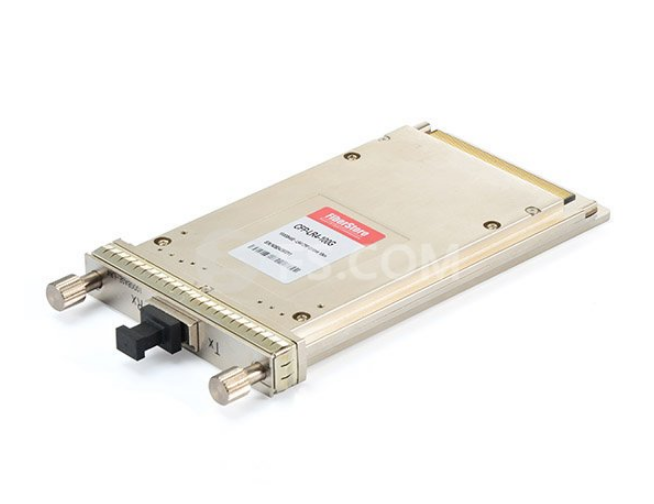
CFP module (C form-factor pluggable) is a Multi-Source Agreement (MSA) that defines a hot-pluggable optical transceiver form factor to enable 40 Gb/s and 100 Gb/s applications, including next-generation High Speed Ethernet (40 GbE and 100 GbE). Pluggable CFP transceivers will support the ultrahigh bandwidth requirements of data communications and telecommunication networks that form the backbone of the Internet. The CFP transceiver features twelve transmit and twelve receive 10Gb/s lanes to support one 100GbE port, or up to three 40GbE ports. Its larger size is suitable for the needs of single-mode optics and can easily serve multimode optics or copper as well.

CFP Module Compared With CXP And QSFP

The CXP transceiver form factor also provides twelve lanes in each direction but is much smaller than the CFP and serves the needs of multimode optics and copper.

The QSFP+ Module is similar in size to the CXP and provides four transmit and four receive lanes to support 40GbE applications for multimode fibre and copper today and may serve single-mode in the future. Another future role for the QSFP may be to serve 100GE when lane rates increase to 25Gb/s.

The Develop Trends Of Next Generation CFP Module

The current generation of modules are large because of heat dissipation issues due to high power consumption. For example, the CFP is rated for up to 24 watts of power dissipation but also needs to have a range of high density electrical connectors to connect to the baseboard. I take this to mean big, hot and heavy.

With the completion of 40/100 Gigabit Ethernet (GbE) optical interface standards (IEEE 802.3ba-2010) and pluggable optical transceiver module specifications, and with the production shipment of first-generation 40GbE/100GbE CFP products underway, optical module vendors are focusing on developing technologies and proving design-ins for their next-generation 40/100GbE pluggable optical transceivers.

The purpose of the CFP MSA is to define a hot-pluggable optical transceiver form factor to enable 40-Gbps and 100-Gbps applications, including next-generation High Speed Ethernet (40 Gigabit Ethernet and 100 Gigabit Ethernet). The pluggable CFP transceivers are designed to support the ultra-high bandwidth requirements of data communications and telecommunications networks.

The key objectives of next-gerneration of CFP modules include significant reductions in module power dissipation and size, which are critical to increasing system port density and reducing overall optical port cost for system vendors and their customers. Critical technologies for tackling these design targets include 4x10G and 4x28G hybrid integrated TOSAs/ROSAs and process improvements in 28G gearbox and CDR ICs. There also may be consideration of uncooled CWDM 28G laser technology for realizing 100GbE optical transceivers in a QSFP+ like form factor for short singlemode fibre.

FS.COM developed the 40GbE CFP module for 10km transmission by using a high-speed four-wavelength CWDM laser diode, through the application of its own low-power-consumption drive technology and high-density mounting technology. Moreover, you can find other 10G, 40G fibre optic transceivers at this website.

Exploiting The Bandwidth of Fiber Optic Cable-Employment By Multiple Users

Sharing the transmission medium

You are the network manager of a company. You have a Source-User link requirement given to you. In response you install a premises fiber optic data link. However, the bandwidth requirements of the specific source users to adapt to the source for bandwidth speed requirements, is much, much less than is available from the fiber optic data link. The tremendous bandwidth of the installed optical fiber cable is being wasted. On the surface, this is not an economically efficient installation.

You want to prove that the install link to the controller of the company, the person who comment on your budget. The controller don’t understand the attenuation benefits of fiber optic cable. The controller doesn’t understand the interference benefits of fiber optic cable. The controller hates waste. He just wanted to see most of the bandwidth of the fiber optic cable used waste nothing. There is a solution to this problem. Don’t just put the huge bandwidth of optical fiber cable, a single, specific, the source user communication needs. Instead, allow it to be shared by a multiplicity of
Source-User requirements. It allows it to carve a multiplicity of fiber optic data links out of the same fiber optic cable.

The technique used to bring about this sharing of the fiber optic cable among a multiplicity of Source-User transmission requirements is called multiplexing. It is not particular to the fiber optic cable. It happens in any transmission medium, such as wire, microwave, etc., the available bandwidth far surpasses any individual Source-User requirement. However, multiplexing is particularly attractive is a fiber optic cable transmission medium.

Conceptually, multiplexing as shown in figure 1. This figure shows the “N” Source-User pairs indexed as 1, 2, … There is a multiplexer provided at each end of the fiber optic cable. The multiplexer on the left takes the data provided by each of the source. It combines these data steams together and sends the resultant steam out on the fiber optic cable. Such a single source to generate data flow sharing the fiber optic cable. The multiplexer on the left performs what is called a multiplexing or combining function. The right of the multiplexer takes the combined stream put out by the fiber optic cable. It separates the combined stream into the individual Source streams composing it. It directs each of these component steams to the corresponding User. The multiplexer on the right performs what is called a demultiplexing function.

A few things should be noted about this illustration shown in Figure 1.

Figure 1: Conceptual view of Multiplexing. A single fiber optic cable is “carved” into a multiplicity of fiber optic data links.

First, the Transmitter and Receiver are still present even though they are not shown. Device is considered to be part of the fiber optic multiplexer is on the left and the receiver are considered to be part of the multiplexer is on the right.

Secondly, the Sources and Users are display close to the multiplexer. Multiplexing to understand this is a common situation. Connectioin from the source to the multiplexer and multiplexer to User is called a tail circuit. If the tail circuit is too long a separate data link may be needed just to bring data from the Source to the multiplexer or from the multiplexer to the User. The cost of this separate data link may counter any savings effected by multiplexing.

Thirdly, the link between the multiplexer, the link in this case realized by the fiber optic cable, is termed the composite link. This is the link, the transportation is by all of the source of the river alone.

Finally, sepatate users are shown in figure 1. However, it may be only user provide separate ports and source of all the common user communication. There may be a change in this. The source user does not need all of the same type. They may be completely different types of data devices serve different applications and different speed requirements.

Within the context of premise data communications a typical situation where the need for multiplexing arises is illustrated in figure 2. This shows a cluster of terminals. In this case there are six terminals. All of these terminals are fairly close to one another. All are at a distance from and want to communicate with a multi-user computer. This can be a multi-use PC or a mini-computer. This situation may arise when all of the terminals are co-located on the same floor of an office building and the multi-user computer is in a computer room on another floor of the building.

The communication connection of each of these terminals could be effected by the approach illustrated in figure 3. Here each of the terminals are connected to a dedicated port at the computer by a separated cable. The cable could be a twisted pair cable or a fiber optic cable. Of course, the six cables are required and the bandwidth of each cable may far exceed the terminal to computer speed requirements.

Figure 2: Terminal cluster isolated from multi-user computer
Figure 3: Terminals in cluster. Each connected by dedicated cables to multi-user computer

Figure 4: Terminals sharing a single cable to multi-user computer by multiplexing

A more economically efficient way of communication connection as shown in figure 4. Here each of the six terminals are connected to a multiplexer. The data streams from these terminals are collected by the multiplexer. The streams are combined and then sent on a single cable to another multiplexer located near the multi-user computer. This second multiplexer separates out the individual terminal data streams and provides each to its dedicated port. The connection going from the computer to the terminals is similarly handled. The six cables shown in figure 3 has been replaced by the single composite link cable shown in figure 4. Cable cost has dropped significantly. Of course, this comes at the cost of two multiplexers. Yet, if the terminals are in a cluster the tradeoff is in the direction of a net decrease in cost.

There are two techniques for carrying out multiplexing on fiber optic cable in the premise environment. These two techniques are Time Division Multiplexing (TDM) and Wavelength Division Multiplexing (WDM). These techniques are described in the sequel. Examples of specific products to

implement these technologies are introduced. These products are readily available from FiberStore.

Time Division Multiplexing (TDM) with Fiber Optic Cable

With TDM a multiplicity of communication links, each for a given Source – User pair, share the same fiber optic cable on the basis of time. The multiplexer set up a continuous sequence of time using the clock. The duration of the period depends on a number of different engineering design factors; most notably the needed transmission speeds for the different links. Each communication link assigned a specific time period, TDM channel, during this period it is allowed to send its data from the source to the client. At this time there is no other link allows sending data. The multiplexer in source side receiving data from the source is connected to it. Then load the data from each source to the TDM channel accordingly. In multiplexer uninstall from each channel at the end of the user data and sends it to the corresponding user.

Wavelength Division Multiplexing (WDM) With Fiber Optic Cable

With WDM a multiplicity of communication links, each for a given Source-User pair, share the same fiber optic cable on the basis of wavelength. The data steam from each source is assigned an optical wavelength. The multiplexer has within it the modulation and transmission processing circuitry. The multiplexer modulates each data stream from each source. After the modulation process the resulting optical signal generated for each source data stream is placed on its assigned wavelength. The multiplexer then couples the totality of optical signals generated for all source data streams into the fiber optic cable. These different wavelength optical signals propagate simultaneously. This is in contrast to TDM.

The fiber optic cable is thereby carved into a multiplicity of data links – each data link corresponding to a different one of these optical wavelengths assigned to the Sources. At the user end the multiplexer receives these simultaneous optical signals. It separates these signals out according to their different wavelengths by using prisms. This constitutes the demultiplexing operation. The separated signal corresponding to the different source user data streams. These are further demodulation. The resulting data separated data streams are then provided to the respective users.

Plastic Optical Fibre Home Networking Solutions

Revolutionary POF plastic optical fibre (POF) home networking solutions to promote the popularization of FTTH, make it at the same time promote IPTV and HDTV service. POF and highly flexibility, security and stability. POF switches more economical, and highly reliability, provide exclusive ultra-high frequency width for each connection. Home network by laying professionals can also use the tool to roll out low-cost networking. This similar to the “garden sprinkler hose” type of connection so that the system installed than any other home networking technologies more convenient and efficient.

Home network is composed of two or more computers, IP telephony, IPTV, printers, cameras, devices together to achieve communication, watching TV, print, monitoring and other purposes, but the home network can share resources, file sharing, Internet access to the Internet, CD-ROM, hard disk and other additional resources.

System can provide up to 1G of exchange capacity and ensure household equipment interconnected transmission quality, high-speed Ethernet for home 100 trillion most reliable technology. System uses a loss factor 150-200dB/km, 1mm diametre plastic optical fibre, coated into 1.5 and 2.2mm white or black twinax cable, 100 metres weights less than 800g, tensile strength greater than 140N, numerical aperture NA of 0.3-0.5, acceptance angle to 60°, fibre optic splice centre alignment deviation of less than 30um, almost does not affect the coupling loss. softness and ultrafine fibre diametre in the new construction or renovation of buildings wiring, wheter walls or wall, skirting, cerpet laying the cable is below, or generally easy to reach places that are hidden requirements, other than the network transmission medium (such as Cat5e or Cat6 Patch Cable) has more advantages, highlight the home network installation easy.

Functions and Features

1. Easy and quick installation;

2. Small volume;

3. Simple design;

4. Through the use of visible light, can rapidly eliminate problems;

5. High cost;

6. Sharing Internet access and file transfer;

7. Multiplayer games;

8. Make Internet phone calls through the Internet, you can greatly reduce the cost of international calls;

9. Watch HD Internet TV (IPTV);

10. As the plastic fibre access provides 100 MB bandwidth, so you can for a long period of time to worry about upgrade issues;

11. You can print, copy, fax and scan, suitable for home office needs, and at the same time network monitoring, no matter where you are, as long as there is a network where you can always see the situation at home.

Fibre Optic Connectors in FTTD Applications

Because of major national policy support, to develop the field of fibre optic products, optical fibre gradual decline in the price of the cost, fibre optic installation and construction are also increasingly simple and convenient, plus high-bandwidth optical fibre, a wide range of applications, from external electromagnetic interference and prevent signal leakage, etc., fibre optic system solutions increasingly facored by customers. FTTx is the use of optical fibre as a transmission channel network physical layer information media, mainly as a network of broadband access. x represent different scenarios applications generally include the following:

1. FTTC (Fibre To The Curb/Cell) is mainly for residential service, ONU telecommunications equipment installed in the side of the road junction box, through the coaxil cable extending from ONU transmission CATV signal, twisted-pair copper networks to transmit voice and fibre optic splice mode signal.

2. FTTB (fibre to the building) service object has two types, one is an apartment building home users, the other is the commercial building companies or business units. ONU devices are generally placed on the bottom into a building (such as the basement), where apartment buildings may be FTTC ONU extension; while commercial buildings because it is a company or business office services enterprises, so that the network transmission performance requirements are higher, network stability and security requirements more stringent.

3. FFTH (Fibre To The Home) optical fibre directly extended to all home users, all-digital network services, to provide users with a varitey of life and enterainment services, such as a doctor at home, online shopping, video on demand, remote training.

4. FTTD (fibre to the desk) refers to the fibre completely replace the traditional copper twisted-pair transmission medium extends directly to the user terminal (such as office computers, printers, etc.), the user terminal to achieve full network access through fibre, improves network transmission bandwidth, extending the transmission distance, and enhance the stability of the network and information security.

The main impact of the test fibre system performance parametres – decay, in addition to the quality of their products with the relevant cable, the most important is the construction and installation process.

1. Fibre polishing method: through on-site hand-grinding, with epoxy adhesive curing, the connector assembly steps to complete the cable connection. Now the basic fibre polishing method should not be adopted, because this way the construction workers demanding technical level, and for the present single-mode systems, Gigabit multimode networks, grinding mode is difficult to achieve, unstable performance.

2. Fibre splicing method: it works by fibre alignment system to align the ends of optical fibers, the use of high-temperature high-pressure arc discharge tip of the principle and performance of fiber-optic high temperature melting, so that fibre splicing together to obtain low loss, low reflection fiber optic fusion splice. Fibre splicing method most widely used at this stage, the most suitable for application in a large number of relatively concentrated fibre termination, especially in the wiring between the application of the cabinet.

3. Fibre Optic Splice method (also called mechanical fibre splice): The whole process does not require cold then hot welding machine, suitable for relatively small number of core optical fibres, optical fibre connecting geographically dispersed, especially suitable for the application in the FTTD.

Fast optical fibre connector is characterized by the application FTTD

Fast fibre optic connectorsis smaller than the volume of the common connector smaller, more convenient wall and desktop installation, to ensure the stability of the optical system
performance and reliability. However, if the conventional optical fibre splicing manner, since the heat-shrinkable sleeve has a length 6 ~ 7mm, the bottom panel 86 of the cartridge mounting space is not deep enough, it can not guarantee performance of the fibre splice and fibre bend radius requirements may result network communication is unstable.

Fast fibre optic connector with fibre embedded in the factory, without gluing and sanding, simple and convenient. Process does not require the entire cold then hot melt machine, greatly reducing the complexity of fibre termination, saving fibre splice time and improve the efficiency of construction.

Fast fibre optic connector with a simple construction and installation requires only a crimping tool to completer fibre optic splice, easy to use and short trainning period; and cold connection equipment investment cost is small, as FTTD solutions to improve the cost-effectiveness.

Fast fibre optic connector construction process does not require an active device, suitable for office construction for harsh environments, especially in pre-construction project, most of them are not powered site environment or to take power inconvenient places.

Fast fibre optic connector can be repeated production, improve the utilisation of fibre head, significant cost savings.

Fast fibre optic connector are available in SC and LC connectors, multi-mode OM2, OM3 and singlemode OS2 Gigabit systems to choose from.

Fast fibre optic connector cold connection steps

Assembly tool (fibre optic cleavers, fibre cable strippers, aramid scissors) and the product material (connector, tail cap, assembly fixtures, 0.9mm cable gripper) the preparation, as shown in Figure 1.

The connector is fixed on the assembly tool, as shown in Figure 2.

Using optical fibre stripping pliers strip the fibre core and the fibre coating sheath, shown in Figure 3

Dipped in pure alcohol, using fibre-cleaning paper bare fibres, as shown in Figure 4.

Optical fibre fixed on the holder, as shown in figure 5.

Using the fibre optic cutter to remove excess length, as shown in Figure 6.

The gripper assembly tool in a guide groove, ensuring the end of fibre alignment U-shaped parts of the connector shown in Figure 7.

Loosen the clamp clip, in the middle of the holder, slow to move forward, until hear the “pop”, as shown in figure 8.

Open all clamps and lock, remove the connector, shown in Figure 9.

Fitted with tail cuff, cold connection completed, as shown in Figure 10.

Fast fibre optic connector as ease of installation and flexibility, more and more customers, are widely used in fibre to the desktop FTTD solution.

A PON Based on Code-division Multiplexing Access

Because of the Internet and broadband networks were introduced, the emerging applications – such as teleconferencing, video on demand, and high quality audio transmission has strict high flux optical access network quality of service (QoS) capabilities. However, the infrastructure of current access networks suffers from limited bandwidth, high network-management costs, poor flexibility, and low security, which prevent networks from delivering integrated services to their users. Due to sophisticated optical components and electronic circuits, optical fiber links has become used in access networks. Passive optical network (PON) and different multiplexing technology is put forward under this background, including the wavelength division multiplexing (WDM), 1 time division multiplex (TDM), 2 and optical code division multiplexing (OCDM).

PONs have been standardized for FTTH solutions and are deployed by network-service providers worldwide. Even though PONs based on TDM (TDM-PON) effectively use fiber bandwidths, they have limitations regarding transmission speed, burst synchronization, security, dynamic bandwidth allocation, and ranging accuracy. Wavelength division multiplexing (WDM) technology has also been proposed for PONs. When used in conjunction with PONs (WDM-PON), this emerging technology becomes more favorable as the required bandwidth increases, but it failed to attract attention from industry due to the high cost of optical component. Other schemes for optical access networks are currently under study worldwide.

Optical code division multiplexing access (OCDMA) systems have attracted attention in recent years, because the number of advantages, including its asynchronous access ability and flexibility of user distribution, support for variable bit rate, traffic and security “bursts” unauthorized users. OCDMA is an very attractive multi-access technique for access systems like local-area networks and the first mile, but no detailed network -design schemes have been developed to date. A PON based on code-division multiplexing access (CDMA) has been proposed using pseudo-random and Walsh codes for user identification. However, signature processing for multiple access is done in the electrical domain using an application – specific integrated circuit (ASIC), and not in the optical field as we are pursuing.

We have developed the OCDMA-PON, a network structure of PON in conjunction with OCDMA, i.e., a different multiple-access technology from TDM and WDM. OCDMA technology achieves signature processing light rather than the electrical domain using an optical encoder/decoder.

Optical-line terminator (OLT) of the optical-code-division multiplexing access/passive optical network (OCDMA-PON) system. Rx, Tx: Receiver, transmitter. OOC: Optical orthogonal code. ODN: Optical distribution network. ONU: Optical network unit. ONT: Optical network termination. n: Counter.

For the forward channels, the source is encoded at the OLT and the downstream signal is transmitted at a wavelength of 1550nm. Every user is a assigned a unique optical orthogonal code and identified by a correlation operation at the optical decoder based on fiber Bragg gratings (FBGs). To reduce multi-user interference (MUI), the nonflattened source spectrum can be compensated by a flatness +compensator before entering the FBG encoder. Another benefit is a flattened source is that it relaxes the accuracy requirements regarding the achievable precision with which the phase can be controlled and maintained stably when the number of users increases. For the backward channel from the optical network unit (ONU) optical network terminal (ONT) to the OLT, the upstream is transmitted at a wavelength of 1310nm. After upstream traffic passes the optical transceiver module, which it is sent to multiple decoders, each of which recovers the information for each user.

Upstream of a stable wavelength is usually required with a stabilized laser source at the ONU’s transmitter. The downstream signal from the OLT to ONU/ONT passes through a circulator to the detector, where the user’s information is separated through optical correlation with his or her unique OCC using a balanced receiver. The downstream control signal is also obtained and the control unit is passed to the network. For the upstream, the signal from the ONU to the OLT is encoded by the OCC for user identification by the optical encoder. This is then transmitted through optical fiber link from tifert. Our scheme has several advantages. For example, any user may add or drop into the network at random and the network is running asynchronously.

Our OCDMA-PON system is composed of an OLT and an ONU. Every ONU is identified by its own cde address. The signal is modulated with both frame information and an address-code sequence. The former is used to complete the data load switch, which help to identify different users.

Figure 1 compares the bit-error rate (BER) with the ONU-transmitter input power for two cases, one affected by interference (for example, MUI or from different noise contributions) and a second based on a back to back configuration. In this case, we assume that the amount ONUs/ ONTs is 30 and the bit rate of downstream flow is 1.25gb/s. We found that the sytem that includes interference exhibits much worse performance than that using the back to the back configuration, with approximately 6dB penalty at a BER of 10−9. For the OCDMA-PON, we confirm that MUI is the dominant degradation source (see Figure 3) and must be included in the network design.

Figure 1. Performance of the OCDMA-PON for back-to-back configuration and with interference. N-active: Number of active users. R-downstream: Downstream-traffic bit rate.

Figure 2 compares the BER performance as the number of active users increases for the CDMA-PON and OCDMA-PON systems. We assumed that the bit rate of downstream traffic is 1.25Gb/s for a fiber-link length of 10km. The OCMDA-PON scheme exhibits a similar performance to the CDMA-PON when the number of users is large. For example, for 30 users and a BER of 10−9, OCDMA-PONs can only increase the number of users compared to that supported by CDMA-PONs by 10%. However, the advantage of OCDMA-PONs over CDMA-PONs becomes obvious when the number of users supported by the OCDMA-PON is small (see Figure 4). Note that the signature is processed in the electrical domain by ASIC with Walsh code for user identification in CDMA-PONs, while the optical domain is used by the FBG encoder/decoder based on source-spectrum flattening and a balanced detector with the prime codes for user identification in OCDMA-PONs. Taking into account the higher bit rate and higher bandwidth offered by OCDMA-PONs based on optical processing of user signatures, we still prefer an OCDMA-PON scheme with intensity modulation. To further improve the performance of the OCDMA-PON, we need to solve the MUI-imposed degradation problems and improve the optical encoder/decoder.

Figure 2. CDMA-PON versus OCDMA-PON comparison as the number of ONUs/ONTs increases. L: Length.

Our OCDMA-PON system is different from classical PONs in that OCDMA is used for multiple-user access instead of TDM or WDM, and the OCDMA-PON scheme combines the advantages of both the PON and OCDMA technologies, including flexible network assembly, fair bandwidth division, differentiated services or QoS in teh physical layer, Asynchronous access, support for variable bit rate and burst, and the security of an unauthorized user traffic. Based on comprehensive comparisons between the OCDMA-PON and the previously studied CDMA-PON, we find that the former scheme exhibits a better BER performance than the latter for small numbers of users.

In summary, OCDMA-PON offers several advantages over CDMA-PON, including higher bit rate, higher bandwidth, and better security against unauthorized users. We continue to work towards realizing an experimental demonstration of the OCDMA-PON system.

Understanding Optical Attenuators

Fibre optic attenuator is used to reduce the power level of optical signal, either in free space or in an optical fibre. They are often used in optical communication systems where the optical signal is too strong and needs to be reduced, in which the attenuation, also called transmission loss, helps with the long-distance transmission of digital signals.

Optical attenuators can take a number of different forms and are typically classified as fixed or variable attenuators. Fixed attenuators can be broken down into either build out style or incorporated into a patch cord. The build out variety is a small (~ 1.25 inch long) attenuator with a male connector interface on one end and a female interface connector on the opposite end. The build out style is typically fabricated with either air gap attenuation or doped fibre attenuation.

Fibre optic attenuators can be designed to use with various types of fibre optic connectors. Commonly used fibre optic attenuators are the female to male type, which is also called a plug fibre attenuator. Another type inline fibre optic attenuator is designed with a piece of fibre optic cable at any length and connectors are installed as the customers request. Fixed value fibre optic attenuators can reduce the optical light power at a fixed level, for example, a 10dB SC fibre optic attenuator will reduce the optical power 10dB and utilize a SC male to female attenuator. Variable fibre optic attenuators are with adjustable attenuation range. There are also attenuation fibre optic patch cables available, their function is the same as attenuators and are used inline.

Variable Attenuator (or ajustable fibre optic attenuator) is a need to provide different under construction decline. The reduction of precision devices for a wide variety of fibre optic transmission lines to carry out scheduled, the amount of light intensity attenuation. There are also handheld variable fibre optic attenuators which are used as test equipment.

Typical attenuation values are between 3 and 20 dB. It is used in optical systems where the optical power from a source is too high for the test equipment in use. Fixed plug type fibre attenuator provides a connector plug (male) and an adapter socket (female) to connect between fibre patch cord and fibre adapter. Fixed plug type optical attenuator introduces an in-line fixed loss that will reduce the source power to an acceptable detection level. The attenuation level should be stable with temperature and wavelength for a stable reliable system.

An optical attenuator uses a segment of attenuating fibre interposed in the optical path. The attenuating fibre is produced by using a solution doping technique to introduce transition or rare earth elements into the fibre’s core. The dopant reduces the transmission of the fibre. The degree of attenuation depends upon the material used as the dopant, the dopant level, and the length of the attenuation segment. In a specific embodiment, an optical attenuator is provided having a first and second signal carrying optical fibres and an attenuating fibre segment, each of which has a core, a cladding substantially coaxial with the core, and a substantially planar end face. The attenuating fibre segment is fusion spliced between the first and second signal carrying optical fibres. In a second embodiment a portion of the cladding of the attenuating fibre is chemically etched.

Wide range variable & inline fibre optic attenuator and the inline fibre optic attenuator are with more accurate attenuation compared with traditional connector type fibre optic attenuators. Variable optical attenuators from FiberStore are specifically designed for use in DWDM networks with individual channel source elements such as add drop multiplexer.