Tag Archives: fiber optic cable

Fibre Optic Patch Panel Best Practices

The fibre optic patch panel, one type of the patch panels, is getting more popular with many expertise and customers getting to use it. It rides the waves of the optic product and meets appropriately our demands. As the fibre is fed through a coupler, the fibre patch panels are a lot easier to install and no hardwiring is needed.

What Is a Fibre Optic Patch Panel?

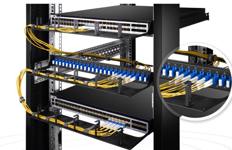
Fibre optic patch panel, also known as fibre distribution panel, serves as a convenient place to terminate all the fibre optic cable running from different rooms into the wiring closet and provides connection access to the cable’s individual fibres. Fibre patch panels are termination units, which are designed with a secure, organised chamber for housing connectors and splice units. Fibre patch panels are available in rack mounted or wall mounted and are usually placed close to terminating equipment (within patch cable reach). Both types can house, organise, manage and protect fibre optic cable, splices and connectors. Rack mount panels also come in flat and angled versions.

fiber patch panel

Why We Use Fibre Optic Patch Panel to Manage Cables?

Of course, if we skip it and just connect all cables directly into the hub, then we will miss the following advantages:

You can label the patch panel so you know which room the cable run goes to. Putting the labels on the cables is tougher to read than labels on a patch panel and there is also a risk of falling off. Having patch panel will become very handy and achieve neat cabling.

Best Practices in the Installation of a Fibre Patch Panel

In this part, we will use a 12 port rack mount fibre optic patch panel as an example. And the main body can be divided into 3 parts, namely cable preparation, splicing, and patch cable installation.

First, prepare fibre optic cable or blown tube as required and secure the network cable to the rear of the panel by using cable ties. For the easy operation, we need to unscrew and remove the splice tray. In addition, we need to cut the cable jacket off to punch down but avoid excess to limit crosstalk or damage. Then, splice input fibres onto the pigtails or field terminate connectors as applicable. Finally, put the cables in the panel form its back. Remove the protective covers of both the adapter and the connector and clean the connectors and place them in the adapters.

Conclusion

In a few words, a fibre optic patch panel gives you a very good cabling organisation. The better cable management can spare you a lot of energy and time in case that you do trivial things. Though many people view it as a waste, I believe that everything has its meaning to exist in the world. What matters most is whether you can take advantage of it and apply it to the situation where it is actually needed.

Introduction of Media Converter

If you want to realize the farther distance connectivity than the actual length the copper cabling you already have can offer, what should you do? Much worse is that no switch is available. Don’t be nervous. The easy solution offered by media converter will be illustrated in this article. Are you poised to have a close understanding of the small device which have blown every people’s minds?

Media Converter

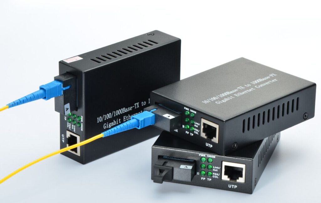
Media converter is a cost-effective and flexible networking device that can connect various fibre optic cable such as multimode, single mode or single strand fibre cable and translates signals between fibre optic cabling and another type of cabling media such as cat6 Ethernet cable. If the distance between two network devices is greater than the copper cabling’s transmission distance, the fibre optic connectivity is required, and can be achieved by a media converter. Fibre connections can greatly extend the reach and reduce electromagnetic interference. Media converters were introduced to the industry in the 1990s, and played an important part of fibre types of cabling system in connection with existing copper-based wiring system. They are also used in metropolitan area network (MAN) access and data transport services to enterprise customers.

converter

There are a wide variety of copper-to-fibre and fibre-to-fibre media converters available that support different network protocols, data rates, cabling and connector types.

Fibre to Fibre Media Converters

One of the key applications for fibre to fibre media converters is to connect between the two network types at the physical network layer. Fibre-to-fibre media converters provide connectivity between dual fibre and single-fibre optic cables. In addition, fibre-to-fibre media converters support conversion from one wavelength to another, including standard wavelengths (1310, 1550) and CWDM wavelengths. It can also extend a MM network across SM fibre with distances up to 140km in a cost-effective way. Fibre-to-fibre media converters are typically protocol independent and available for Ethernet, and TDM applications.

Copper-to-Fibre Media Converters

Supporting the IEEE 802.3 standard, Ethernet copper-to-fibre media converters provide connectivity for Ethernet, Fast Ethernet, Gigabit and 10 Gigabit Ethernet devices. Some converters support 10/100 or 10/100/1000 rate switching, enabling the integration of equipment of different data rates and interface types into one seamless network. The copper-to-fibre conversion carried out by a media converter allows two network devices having copper ports to be connected across long distances by means of fibre optic cabling.

For twisted pair ports( RJ-45 ports), they can transfer signal of SFP port into signal of RJ-45 port for transmission. SFP port is mainly connected with upstream equipment while RJ45 port is connected to the downstream device.

Conclusion

In the data centre, fibre media converters pose as an alternative solution for switches. Next time you are in this condition, don’t hurry to throw the copper cable away, just an easy click on FS.COM, then all mess will be eliminated. Choose a suitable media converter and it will be delivered quickly to your address. The media converter provided by FS.COM is very small so won’t occupy too much space and can be deployed in a variety of networks and applications.

What Are the Components of Optical Fiber

What are the components of optical fiber? A typical optical fiber comprises three main components: the core, which carries the light; the cladding, which surrounds the core with a lower refractive index and contains the light; and the coating, which protects the fragile fiber within.

Core

The core, which carries the light, is the smallest part of the optical fiber. The optical fiber core is usually made of glass, although some are made of plastic. The glass used in the core is extremely pure silicon dioxide (SiO2), a material so clear that you could look through 5 miles of it as though you were looking through a household window.

In the manufacturing process, dopants such as germania, phosphorous pentoxide, or alumina are used to raise the refractive index under controlled conditions.

Optical fiber cores are manufactured in different diameters for different applications. Typical glass cores range from as small as 3.7um up to 200um. Core sizes commonly used in telecommunications are 9um, 50um and 62.5um. Plastic optical fiber cores can be much larger than glass. A popular plastic core size is 980um.

Cladding

The cladding is surrounding the core and providing the lower refractive index to make the optical fiber work. When glass cladding is used, the cladding and the core are manufactured together from the same silicon dioxide-based material in a permanently fused state. The manufacturing process adds different amounts of dopants to the core and the cladding to maintain a difference in refractive indexes between them of about 1%.

A typical core may have a refractive index of 1.49 at 1300nm while the cladding may have a refractive index of 1.47. These numbers, however, are wavelength dependent. The core of the same fiber will have a different refractive index at a different wavelength.

Like the core, the cladding is manufactured in standard diameters. The two most commonly used diameters are 125um and 140um. The 125um cladding typically supports core sizes of 9um, 50um, 62.5um and 85um. The 140um cladding typically has a 100um core.

Coating

The coating is the ture protective layer of the optical fiber. The coating absorbs the shocks, nicks, scrapes, and even moisture that could damage the cladding. Without the coating, the optical fiber is very fragile. A single microscopic nick in the cladding could cause the optical fiber to break when it’s bent. Coating is essential for all-glass fibers, and they are not sold without it.

The coating is solely protective. It does not contribute to the light-carrying ability of the optical fiber in any way. The outside diameter of the coating is typically either 250um or 500um.  Generally the coating is colorless. In some applications, however, the coating is colored, so that individual optical fibers in a group of optical fibers can be identified.

The coating found on an optical fiber is selected for a specific type of performance or environment. Once of the most common types of coating is acrylate. This coating is typically applied in two layers. The primary coating is applied directly on the cladding. This coating is soft and provides a cushion for the optical fiber when it is bent. The secondary coating is harder than the primary coating and provides a hard outer surface. Acrylate, however, is limited in temperature performance. A typical acrylates may perform at temperatures up to 125º C.

Silicone, carbon, and polyimide are coatings that may be found on optical fibers that are used in harsh environments such as those associated with avionics, aerospace, and space. They may also be used on optical fibers designed for mining, or oil and gas drilling.

Standards

While many combinations of core and cladding sizes are possible, standards are necessary to ensure that connectors and equipment can be matched properly. This is especially important when dealing with components as small as those used in fiber optics, where even slight misalignments can render the entire system useless.

Two organizations publish standards that define the performance of optical fibers used in the Telecommunications industry; they are the Telecommunications Industry Association (TIA)and the International Telecommunications Union (ITU). While TIA and ITU publish many standards on optical fiber, the key standards that you should be familiar with ANSI/TIA-568-C.3, ITU-TG.653, ITU-TG.655 and ITU-T G.657.

The ANSI/TIA-568-C.3 standard is applicable to premises optical fiber cabling components. The ITU standards are applicable to Single Mode Fiber Optic Cable. The following are their descriptions:

>ITU-TG.652: Characteristics of a single mode optical fiber and cable

>ITU-T G.655: Characteristics of a dispersion shifted single mode optical fiber and cable

>ITU-T G.657: Characteristics of a non-zero dispersion-shifted single mode optical fiber and cable

These standards contain important information that defines the performance of the optical fiber, Fiber Optics Cables, and components such as Fiber Optics Connectors and splices.

Materials

Optical fibers are commonly made with a glass core and glass cladding, but other materials may be used if the fiber’s performance must be balanced with the cost of installing the fiber, fitting it with connectors, and ensuring that it is properly protected from damage. In many cases, fibers must run only a short distance, and the benefits of high quality all glass fibers become less important than simply saving money. There are also circumstances in which the fibers are exposed to harsh conditions, such as vibration, extreme temperature, repeated handling, or constant movement. Different fiber classifications have evolved to suit different conditions, cost factors, and performance requirements.

The major fiber classifications by material are

Glass fibers: These have a glass core and glass cladding. They are used when high data rates, longtransmission distances, or a combination of both are required. Glass fibers are the most fragile of the various types available, and as a result they must be installed in environments where they will not be subjected to a great deal of abuse, or they must be protected by special cables or enclosures to ensure that they are not damaged.

Glass fibers are commonly found in long-distance data and interbuilding and interoffice networking applications.

Plastic clad silica (PCS): These fibers have a glass core and plastic cladding. The core is larger than all-glass fiber; typically, 200µm with a cladding thickness of 50µm. Like a siliconecoated glass optical fiber, the plastic coating of a PCS optical fiber is typically used with a thermo-plastic buffer that surrounds the plastic cladding. A typical PCS fiber specification would be 200/300µm. The plastic cladding also serves as a protective layer for the glass core, so the coating normally found on all-glass fiber is not included on PCS fibers. PCS fibers are typically used for industrial sensing applications and medical/dental applications.

Hard-clad silica (HCS): These fibers are similar to PCS fiber but they have a glass core with cladding made of a hard polymer or other material, typically stronger than other cladding materials. Hard-clad silica fiber is commonly used in locations where ruggedness is a prime consideration, such as manufacturing, factory automation, and other areas where shock and vibration would render standard glass fibers unreliable. HCS optical fibers are typically much larger than glass optical fibers. A very popular size is 200/230µm.

Plastic fiber: These fibers have a plastic core and plastic cladding. They are selected for their low cost, ruggedness, and ease of use, and are installed where high bandwidth and long transmission distances are not required. While plastic fibers are unsuited for long-distance, high performance transmissions, they can still carry signals with useful data rates over distances of less than 100m. A very popular size is 980/1000µm. Plastic fiber is typically designed for visible wavelengths in the 650nm range. Some typical locations for plastic fiber include home entertainment systems, automotive, and manufacturing control systems. They may also be used in links between computers and peripherals and in medical equipment.

The advantages of large core plastic optical fiber

It is easy to get excited about the high bandwidth and long distance transmission capabilities of glass optical fiber. It clearly outperforms any other medium. However, many applications do not require a high bandwidth over great distances. There are many applications for optical fiber in your home. You may already have a home entertainment system that uses plastic optical fiber, or you may own a car that uses plastic optical fiber to connect audio devices or a DVD changer. None of these applications requires high bandwidth over great distances. These applications are ideal for large core plastic optical fiber.Plastic optical fiber is typically designed to operate at a visible wavelength around the 650nm range. Being able to see the light as it exits the optical fiber has a significant advantage; no expensive test equipment is required. A power meter is needed to measure the light exiting a glass optical fiber operating in the infrared range. Power meters can cost more than your home entertainment system.

The large core of the plastic optical fiber has another advantage over small glass fibers: it is easy to align with another fiber or a light source or detector. Imagine aligning two human hairs so that the ends touch and are perfectly centered. Now imagine doing the same thing with two uncooked spaghetti noodles.

Exploiting The Bandwidth of Fiber Optic Cable-Employment By Multiple Users

Sharing the transmission medium

You are the network manager of a company. You have a Source-User link requirement given to you. In response you install a premises fiber optic data link. However, the bandwidth requirements of the specific source users to adapt to the source for bandwidth speed requirements, is much, much less than is available from the fiber optic data link. The tremendous bandwidth of the installed optical fiber cable is being wasted. On the surface, this is not an economically efficient installation.

You want to prove that the install link to the controller of the company, the person who comment on your budget. The controller don’t understand the attenuation benefits of fiber optic cable. The controller doesn’t understand the interference benefits of fiber optic cable. The controller hates waste. He just wanted to see most of the bandwidth of the fiber optic cable used waste nothing. There is a solution to this problem. Don’t just put the huge bandwidth of optical fiber cable, a single, specific, the source user communication needs. Instead, allow it to be shared by a multiplicity of
Source-User requirements. It allows it to carve a multiplicity of fiber optic data links out of the same fiber optic cable.

The technique used to bring about this sharing of the fiber optic cable among a multiplicity of Source-User transmission requirements is called multiplexing. It is not particular to the fiber optic cable. It happens in any transmission medium, such as wire, microwave, etc., the available bandwidth far surpasses any individual Source-User requirement. However, multiplexing is particularly attractive is a fiber optic cable transmission medium.

Conceptually, multiplexing as shown in figure 1. This figure shows the “N” Source-User pairs indexed as 1, 2, … There is a multiplexer provided at each end of the fiber optic cable. The multiplexer on the left takes the data provided by each of the source. It combines these data steams together and sends the resultant steam out on the fiber optic cable. Such a single source to generate data flow sharing the fiber optic cable. The multiplexer on the left performs what is called a multiplexing or combining function. The right of the multiplexer takes the combined stream put out by the fiber optic cable. It separates the combined stream into the individual Source streams composing it. It directs each of these component steams to the corresponding User. The multiplexer on the right performs what is called a demultiplexing function.

A few things should be noted about this illustration shown in Figure 1.

Figure 1: Conceptual view of Multiplexing. A single fiber optic cable is “carved” into a multiplicity of fiber optic data links.

First, the Transmitter and Receiver are still present even though they are not shown. Device is considered to be part of the fiber optic multiplexer is on the left and the receiver are considered to be part of the multiplexer is on the right.

Secondly, the Sources and Users are display close to the multiplexer. Multiplexing to understand this is a common situation. Connectioin from the source to the multiplexer and multiplexer to User is called a tail circuit. If the tail circuit is too long a separate data link may be needed just to bring data from the Source to the multiplexer or from the multiplexer to the User. The cost of this separate data link may counter any savings effected by multiplexing.

Thirdly, the link between the multiplexer, the link in this case realized by the fiber optic cable, is termed the composite link. This is the link, the transportation is by all of the source of the river alone.

Finally, sepatate users are shown in figure 1. However, it may be only user provide separate ports and source of all the common user communication. There may be a change in this. The source user does not need all of the same type. They may be completely different types of data devices serve different applications and different speed requirements.

Within the context of premise data communications a typical situation where the need for multiplexing arises is illustrated in figure 2. This shows a cluster of terminals. In this case there are six terminals. All of these terminals are fairly close to one another. All are at a distance from and want to communicate with a multi-user computer. This can be a multi-use PC or a mini-computer. This situation may arise when all of the terminals are co-located on the same floor of an office building and the multi-user computer is in a computer room on another floor of the building.

The communication connection of each of these terminals could be effected by the approach illustrated in figure 3. Here each of the terminals are connected to a dedicated port at the computer by a separated cable. The cable could be a twisted pair cable or a fiber optic cable. Of course, the six cables are required and the bandwidth of each cable may far exceed the terminal to computer speed requirements.

Figure 2: Terminal cluster isolated from multi-user computer
Figure 3: Terminals in cluster. Each connected by dedicated cables to multi-user computer

Figure 4: Terminals sharing a single cable to multi-user computer by multiplexing

A more economically efficient way of communication connection as shown in figure 4. Here each of the six terminals are connected to a multiplexer. The data streams from these terminals are collected by the multiplexer. The streams are combined and then sent on a single cable to another multiplexer located near the multi-user computer. This second multiplexer separates out the individual terminal data streams and provides each to its dedicated port. The connection going from the computer to the terminals is similarly handled. The six cables shown in figure 3 has been replaced by the single composite link cable shown in figure 4. Cable cost has dropped significantly. Of course, this comes at the cost of two multiplexers. Yet, if the terminals are in a cluster the tradeoff is in the direction of a net decrease in cost.

There are two techniques for carrying out multiplexing on fiber optic cable in the premise environment. These two techniques are Time Division Multiplexing (TDM) and Wavelength Division Multiplexing (WDM). These techniques are described in the sequel. Examples of specific products to

implement these technologies are introduced. These products are readily available from FiberStore.

Time Division Multiplexing (TDM) with Fiber Optic Cable

With TDM a multiplicity of communication links, each for a given Source – User pair, share the same fiber optic cable on the basis of time. The multiplexer set up a continuous sequence of time using the clock. The duration of the period depends on a number of different engineering design factors; most notably the needed transmission speeds for the different links. Each communication link assigned a specific time period, TDM channel, during this period it is allowed to send its data from the source to the client. At this time there is no other link allows sending data. The multiplexer in source side receiving data from the source is connected to it. Then load the data from each source to the TDM channel accordingly. In multiplexer uninstall from each channel at the end of the user data and sends it to the corresponding user.

Wavelength Division Multiplexing (WDM) With Fiber Optic Cable

With WDM a multiplicity of communication links, each for a given Source-User pair, share the same fiber optic cable on the basis of wavelength. The data steam from each source is assigned an optical wavelength. The multiplexer has within it the modulation and transmission processing circuitry. The multiplexer modulates each data stream from each source. After the modulation process the resulting optical signal generated for each source data stream is placed on its assigned wavelength. The multiplexer then couples the totality of optical signals generated for all source data streams into the fiber optic cable. These different wavelength optical signals propagate simultaneously. This is in contrast to TDM.

The fiber optic cable is thereby carved into a multiplicity of data links – each data link corresponding to a different one of these optical wavelengths assigned to the Sources. At the user end the multiplexer receives these simultaneous optical signals. It separates these signals out according to their different wavelengths by using prisms. This constitutes the demultiplexing operation. The separated signal corresponding to the different source user data streams. These are further demodulation. The resulting data separated data streams are then provided to the respective users.

Fiber Optic Patch Cable Of Cabling System Management

For cabling, telecommunication rooms and equipment rooms are the convergence of three businesses including data, voice and image, and its importance is self-evident. So making great efforts in their overall design, equipment stereotypes, hardware configuration, maintenance and other aspects of construction. However, the construction side always tends to ignore the largest number of equipment maintenance and installation of security – fiber optic cables and fiber patch cables in the telecommunications rooms and equipment rooms. While ignoring the problem will bring us a lot of trouble to the machine room management therefore I believe that it is necessary to have proper fiber optic patch cord management operations.

In general, reasonable patch cables management can be divided into five processes: planning, preparation, wiring, testing and verification.

1. Planning

For patch cables management, should be prepared the requirements planning including present and future.

1.1 Change Requests. A variety of management activities, move, add or change (MAC) all began in the change requests. Change requests must contain all the necessary information about starting the planning procedures.

1.2 Search Records. After receiving the request table, searching the coping recording, in order to determine the circuit paths used.

1.3 Correct Routing. Before determine the correct length of fiber optic patch cord, we should first find out the best route between the ports. Usually the shortest route is passing from the horizontal and vertical cable. Moreover shall not obstruct or interfere with the other jumpers or connectors in the distribution frame. When select fiber optic patch cables, should avoid excessive laxity, ensure the appearance clean and tidy. Jumper too tight will increase the pulling force of connectors, whereas overwork slack will bring trouble to jumper management, increase the patch panel’s management difficulty.

2. Preparation

Before the implementation of management, you should do prepare as much as possible, to research the management records. Determine the label information of connection and reconnect port location and the relevant ports.

2.1 First check the require patch cable model, and then check the quality of the jumper. To ensure the quality of the jumper is correct, need to check whether the jumper is damaged. In order to check it is damaged or not, of course you can from the appearance of the jumper, if possible, use professional equipment to check.
2.2  Then check the situation of the require connecting portion, in order to avoid physical damage to the connection parts.
2.3  Finally need to clean the jumper joints and the connecting parts.

There are two ways available to clean the fiber connectors: contact and non-contact.

Contact Cleaning Method:
(1). Wiping paper and anhydrous alcohol, using raw wood pulp with special processing technology, ultra-low dust, pure texture, high performance water absorption, delicate, will not scratch the surface swabbed, with a low dust wipe with no water-alcohol wipe on fiber optic connectors;
(2). Non-woven fabric, does not produce lint, tough, without any chemical impurities, silky soft, does not cause allergic reactions, and not easy to fluff and hair loss, as the ideal choice for cleaning fiber optic connectors or pins on the production or testing, wipe fiber optical connector with no water-alcohol;
(3). Cleaning cotton swabs, specifically designed for ceramic casing internal cleaning or for cleaning the ferrule end face of the flange (or adapter) which is not easy reached;
(4). Professional cleaner, fiber optic connector special cleaner uses special cleaning wiping belt, mounted in a scramble enclosure, no alcohol, each cleaning is very effective and produces a new surface, convenient and practical.

Non-Contact Cleaning Method:

(1). Ultrasonic cleaning method, it replaces clean liquid into ultrasonic “column” to the connector end surface, and waste recycling and sucked clean in the same small space;
(2). High-pressure blowing method, its principle is at the connector end first coated with cleaning fluid, and then use high-pressure gas blowing at the connector end surface;

2.4 Check the fiber optic connector cleanliness

After finish cleaning fiber optic connectors, must check the terminated surface. General practice is to use a magnifying glass 100, 200 times or 400 times to check, the figure below shows the fiber end-face in a pure state and a contaminated state.

Patch cable management person, no matter using which method mentioned above, for some serious pollution or difficult to clean connectors, needs to use cotton swabs, alcohol and other cleaning fluid to handle.

After this series of preparatory work, it means the wiring work of patch cable management is to expand.

3. Wiring

Patch panel installation, should base on operational procedures to complete various stages of any work. Patch cable construction kinks, glitches, bad pinch and bad contact are likely to significantly reduce the jumper performance. To avoid such problems, you should focus on the following factors:

(1). Bending radius
The minimum bending radius jumper allows need to comply with the jumper manufacturer operating specifications.

Standard says, the minimum bend radius of unshielded twisted pair (UTP) cable should be at four times as the diameter of fiber optic cable, shielded twisted-pair cable is as eight times as the diameter of fiber optic cable. The minimum bend radius of 2-core or 4-core horizontal cable is greater than 25mm, if the bending radius is smaller than this standard, it may lead to a change in the relative position of the wire, resulting in reduced transmission performance.

(2). Jumper tensile and stress
During wiring process, not excessive force, otherwise it may increase the stress on jumpers and connectors, resulting in decreased performance.

(3). Bundle
The jumper is not always needed bundling, if bundled strapping manufacturers need to comply with the principle, not tied too tight, otherwise it will cause a twisted pair variant. Do not over-tighten the clamp, the jumper should be able to freely rotate. Please use a dedicated product, consider choosing repeated use products without tools, such as nylon sticking with buckle belt.

4. Testing

Even after the jumper wiring completed, but may be that if the fiber links or copper links are in full compliance with operating specifications or cabling international and national standards. Then it should be fiber or copper testing, only in accordance with the testing standards, then can determine whether it passes the test standard.

5. Verification

(1). It is worth spending the time to the final visual inspection of the connection. Ensure that the jumper relaxation not knot, is not a cabinet door clamp.

(2). The final step is based on the existing configuration update records, close and have completed the change request related work orders.

Now the fiber optic cable is one of the most important components of integrated wiring system, especially good management operation of fiber jumpers in the data center project, is particularly prominent. Believe that as construction management personnel reasonably jumper management operates, will make the entire comprehensive wiring system become advanced, scientific, practical and reliable.

With the large number applications of 10G/40G/100G network in data center, on-site installation and management of fiber optic patch cable becomes increasingly important, the jumpers management sometimes affect the overall channel attenuation, good management ensures fiber channel data transmission in the most excellent condition, process-oriented operations such as planning, preparation, wiring, testing and verification have important significance to assurance the quality of the system.

NASA and Astro Technology collaborate to Develop Offshore Fiber-Optic Tehnology

It is recorded that the Houston-based Astro Technology Inc. and the National Aeronautics and Space Administration (NASA) has cooperated and developed a new fiber optic monitoring system this year on two oil platforms offshore West Africa.

The new system Tendon Tension Monitoring System (TTMS) utilizes a fiber optic strain gauge system and a series of sensor clamps to measure the tension on subsea risers and pipelines. It is installed in March on two platforms at the Okume complex for Hess Corporation’s subsidiary Hess-Equatorial Guinea.

According to Nasa, the system can sense any stresses along the platform’s four legs and streams the data in real time, allowing operators to make alterations required to maintain platform’s stability.

During the offshore research, the team attached 16 clamps to two separate drill platforms by commercial divers, using fiber optic cables to send real-time data streaming to a control room on each drill platform.

Astro Technology is specialized in instrumentation and monitoring technologies with a focus on real-time fiber optic sensory systems for oil and gas, has successfully used fiber optic monitoring systems at depths of up to 7,500 feet. This technology was developed as a result of a space Act Agreement, which permits NASA to partner with outside organizations to bring NASA expertise, assets or information to a wide community. Space Act Agreement, which date back to 1958, allows NASA to work with a broad spectrum of partners from all public and private sector discipline, according to NASA’s website.

Nasa chief technologist, Mason Peck, said: “What we learn from testing this technology on the oil platforms will benefit a broad range of terrestrial and space applications, and shows Nasa’s technology investments support America’s future in space and improve our lives here on Earth.”

Published by FiberStore, industry news – www.fs.com

Choosing Fiber Optic Cable Or Copper Wire For Communication

When computer networks were invented, copper wiring was used for the cables that handled the Internet. But nowadays fiber optic cable is more often used for new cabling installations and upgrades, including backbone, horizontal, and even desktop applications. They are more favored for today’s high-speed data communications, such as Gigabit Ethernet, FDDI, multimedia, ATM, SONET, Fiber Channel, or any other network that requires the transfer of large, bandwidth-consuming data files, particularly over long distances.

Fiber optic cables offer a number of advantages over copper.

Lower Cost–While fiber optic cable itself is cheaper than an equivalent length of copper cable, fiber optic cable connectors and the equipment needed to install them are more expensive than their copper counterparts.

Long Distance And High Capacity–Fiber optic cables carry communication signals using pulses of light. Only fiber optics can go the long distance. Not only is fiber optic cable capable of carrying far more data than copper, it also has the ability to carry that information for much longer distances. Fiber to the Home (FTTH) installations are becoming more common as a way to bring ultra-high speed Internet service (100 Mbps and higher) to residences.

Higher Bandwith–Fiber has a higher bandwidth than copper. Example: cat6 network cable is classified by the Telecommunications Industry Association (TIA) to handle a bandwidth up to 600 MHz over 100 meters, which theoretically, could carry around 18,000 calls at the same time. Multimode Fiber, on the other hand, would have a bandwidth of over 1000 MHz which could carry almost 31,000 simultaneous calls.

Adaptable To Any Environment–Fiber optic cables don’t mind roughing it. Since fiber optic cables are glass-based, glass fibers don’t only escape interference. They are virtually free from the threat of corrosion, too. While copper cabling is sensitive to water and chemicals, fiber optic cabling runs almost no risk of being damaged by harsher elements. Fiber optic cables can be used outdoors — and in close proximity to electrical cables –without concern. As a result, fiber optic cable can easily endure “living conditions” that coaxial cable just can’t, such as being put in direct contact with soil, or in close proximity to chemicals.

For reasons stated above, fiber optic cable is a more reliable means of communication. While the decision on using copper cables or fiber optic cables may be difficult. It will often depend on your current network, your future networking needs, and your particular application, including bandwidth, distances, environment, and cost. While in some cases, copper may be a better choice.

Copper works on simple ADSL connections since there is not much of a distance from a modem to a phone jack on a wall. Copper usually transmits data without loss at distances of two kilometers or less. On top of all that, the demand for bandwidth in an ADSL connection is often low enough (around 6 to 8 Mbps on average) to use copper wires.

As the mature of fiber optic cables production, they are more affordable. Choosing fiber optic cables or copper wire for your communication is completely up to your future networking needs and your particular application.