Monthly Archives: September 2016

Advice on Patch Cable Selection for Optical Transceiver

Fibre optic network connection can’t be achieved without optical transceiver and patch cable. Optical transceiver varies from transmission media, interface, transmission distance, data rate, and brand, for example, SFP for 1000Mbps, SFP+ for 10G, QSFP+ for 40G, CFP and QSFP28 for 100G. It’s not difficult to identify these optical transceivers. But when you connect the optical transceiver to the patch cable, many details need to be noticed. This article will give you advice on how to choose the suitable patch cable for your optical transceiver.

Transmission Media—Copper & Fibre

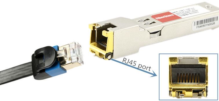
According to transmission media of fibre optic and copper, transceivers can be divided into two kinds, copper based transceivers and fibre optic based transceivers. MSA has defined several copper based transceiver like: 100BASE-T, 1000BASE-T and 10GBASE-T. Copper transceivers are available in GBIC, SFP and SFP+ form factors, which usually has an RJ45 interface. So Cat5/6/7 cables are typically used to connect with the transceivers. Maybe Cat8 will be researched and developed to support higher data rate up to 40G sooner or later.

optical-transceiver-rj45-interface

As to fibre optic transceivers, things are more complex. For that fibre optic transceivers require different fibre patch cords which have more types. Fibre patch cables cover single-mode and multimode. Single-mode patch cable can be classified into OS1 and OS2. While multimode cables can be divided into OM1, OM2, OM3, OM4 cable. Different cables are used in different applications. Single-mode cable can support long distance transmission and multimode cable for short distance link. If the transmission distance is shorter than 500 metres, multimode patch cable is suggested. For long distance transmission, single-mode transmission is suggested. You patch-cable
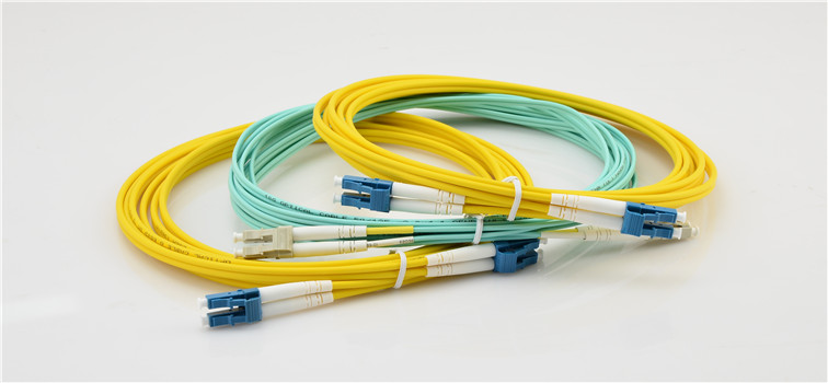
should also consider that the transmission data rate can also affect the transmission distance. Let’s look at the following point.

Supported Distance and Data Rate

MSA has defined a variety of transceivers that can support different transmission distances and data rates. When you buy a fibre optic transceiver, you will find the data rate, wavelength, distance, etc. on its labeling. The following table show the basic information of most often used transceivers and supported cable type.

Description Wavelengh Data Rate Cable Type Distance
SX 850nm 1G MM 500 m
LX 1310nm 1G SM 8 km
EX 1310nm 1G SM 40 km
ZX 1550nm 1G SM 70 km
SR 850nm 10G MM 300 m
LR 1310nm 10G SM 10 km
ER 1550nm 10G SM 40 km
ZR 1550nm 10G SM 80 km
SR4 850nm 40G MM 100 m
SR10 850nm 100G MM 100 m
LR4 1310nm 40G SM 10 km

As mentioned before, single-mode patch cable is better for long distance transmission and multimode patch cable for short distance transmission. Actually single-mode patch cords can be used for different data rates in both long and short distances. But single-mode fibre optic cable will cost more. To achieve reliable performance in short distances with cost effective solutions, you should know the performance of multimode fibre optic cables. The following chart provides the detailed transmission distances and data rates information for different multimode fibre optic cables over wavelength of 850 nm for your reference.

Fibre Type 1G 10G 40/100G
OM1 300 m 36 m N/A
OM2 500 m 86 m N/A
OM3 1 km 300 m 100 m
OM4 1 km 550 m 150 m
Transceiver Interfaces

The selection of patch cable for transceiver should also consider the interfaces through which patch cords is connected to the transceiver. In addition, transceiver usually used one port for transmitting and one port for receiving. Generally, fibre optic transceivers usually employs duplex SC or LC interfaces. However, for BiDi transceivers only one port is used for both transmitting and receiving. Thus, simplex patch cord is used with BiDi transceiver.

Some 40G/100GBASE QSFP+ transceivers used MTP/MPO interfaces, which should be connected to the network with multi-fibre patch cords attached with MTP/MPO connectors. If these ports are used for 40G to 10G or 100G to 10G connection, then fanout patch cable should be used. For example, a MTP to 8 LC fanout cable can splitter 40G data rate to four 10G data rate.

Summary

Next time when you select patch cords for your fibre optic transceivers, you can consider these factors like transmission media, transmission data rate and distance, transceiver interfaces. FS.COM offers a wide range of fibre optic transceivers and patch cords. Custom service is also available. Any problem, please contact us via sales@fs.com.

How to Make Your Own Ethernet Cables?

Ethernet patch cables are indispensable for network. However, Ethernet patch cables are more expensive than bulk cables and the pre-terminated lengths are not always that you need. So it’s quite necessary to know how to wire Ethernet cable by yourself. This article will show you detailed steps of making your own Ethernet patch cable.

Materials You Need
Bulk Ethernet cable

Usually people will choose Cat5e cable. Cat5e cable is a little different from Cat5. It can handle data rate up to 1000Mbps. Cat5e is suitable for Gigabit Ethernet and experiences much lower levels of near-end crosstalk (NEXT) than Cat5. So in most applications, Cat5 has been superseded by Cat5e. Except Cat5e, you may also choose Cat6 cables which have better performance. Cat6 cable has twice the bandwidth of Cat5. It’s ideal for supporting 10 Gigabit Ethernet. Select the cable type and then buy the lengths of the cable you need.

RJ45 Connectors for Cat5e or for Cat6

RJ45 connectors are often used for telephone and network. RJ45 connectors include a variety of types for Cat 5e or Cat6, such as shielded, strain relief boots, 2 prong or 3 prong, etc. Whatever, you need to select the one suitable for your application. FS.COM provides plenty of RJ45 connectors meeting a high standard of safety quality.

rj45-connectors

RJ-45 Crimping Tool

RJ45 crimping tool is designed to quickly, strip, crimp and cut the wires in an easy operation. FS.COM supplies various types of high quality crimping tools. With this kind of tool, you can get precise and reliable terminations every time.

fs-crimping-tool

Steps for Wiring Ethernet Cable
Step 1. Strip Outer Sheath

Use your stripper on your crimping tool to strip 1 inch (2.5 cm) sheath from the end of the cable. Insert the cable into the stripper portion of the crimping tool and squeeze it tight. When squeezed, rotate the crimping tool around the cable a full 360°. At last, pull away and the sheath will be stripped. If you break the internal twisted wires by accident, just cut the broken wire and strip again. So when you measure the cable length, you should better leave spare inches in case things happen like this.

Step 2. Untwist and Arrange Wire

After stripping the sheath, you can find 8 color-coded wires inside. Then you need to untwist the internal wires and arrange them into a proper wiring scheme for RJ45 connector. There are two kinds of color codes standards: T568A and T568B. The color order is important to get correct. No matter which standards you choose, you should arrange the color-coded wires in the same order on both sides. Here recommend you T568B color-coded wiring. The following are about pins and colors used in T568B standards.

Pin1—White/Orange
Pin2—Orange
Pin3—White/Green
Pin4—Blue.
Pin5—White/Blue
Pin6—Green.
Pin7—White/Brown
Pin8—Brown

Step 3. Insert the wire into RJ45 connector

Before insert the wire into RJ45 connector, you need to cut down the wire to fit in the connector. Bring the wires together and cut them down in an even line with the cutting tool on the crimping tool. Then insert the wires into the connector in the right order. Ensure each wire fits into each groove in the connector. The wires should be inserted until the sheathing is inside the connector, just beyond the crimp portion of the connector.

insert-wire-into-rj45

Step 4. Crimp

Put the connector into the crimping tool carefully until the connector can’t go in any further. Squeeze the crimping tool very tightly and release. Then squeeze the the crimping tool again to make sure that all of the pins are pushed down on the connector. When finishing crimping, check that if all pins are all crimped down. If the pins are all down, tug the connector slightly to make sure that it is securely attached to the wire.

crimp-rj45

Step 5. Test

Before installing the cable, you should better take a test with an Ethernet cable tester. If the Ethernet cable doesn’t work, look closely at each end and see if you can find the problem. Usually the problem is caused because a wire ends up in the wrong place or one of the wires makes no contact or poor contact. You should also check if the color is in the right order. If the color order is wrong, then cut the end off and start again.

Summary

Sure, you can buy Ethernet cables from the store directly. But if you need to make your own cable with special lengths, then you are lucky to read this article. Remember that the Ethernet cable should be no more than 100 metres or 328 feet. Because the cable performance will be influenced by the over length. For bulk cables, RJ45 connectors, crimping tools, and network testers, etc., you can get all from FS.COM. Hope you can make your own Ethernet cable successfully.

How to Distinguish T568A and T568B of RJ45 Ethernet Cable Wiring?

The network cable can be easily found in our daily life. Ethernet network cable is color-coded if you look at its wires carefully. Color-coded wiring sequences exist as a cabling industry standard. Thus, cabling technicians can save a lot of time making cable termination on both ends by following others’ work without guessing or deciphering the function and connections of each wire pair. This article will tell T568A and T568B standards that the Ethernet cable jack wiring follows. T568A vs T568B differences are also mentioned.

What Are T568A and T568B Standards?

RJ45 conductor data cable contains 4 pairs of wires. Each one consists of solid colored wire and a strip of the same color. There are two wiring standards for RJ45 Ethernet cable wiring: T568A and T568B. T568A and T568B are the two wiring standards for RJ45 connector data cable. T568A was specified by TIA/EIA-568-A wiring standards in 1995. Later it was replaced by the TIA/EIA 568-B standard in 2002 and has been updated since. Both standards define the T568A and T568B pin-outs for using unshielded twisted pair cable and RJ45 connectors for Ethernet connectivity. These two standards and pin-out specification appear to be related and interchangeable. But they still have differences and should not be used interchangeably.

T568A vs T568B

RJ45 Colour-Coded Scheme

The RJ45 patch cable has 8 color-coded wires and the plugs have 8 pins and conductors. Eight wires are used as 4 pairs, each representing positive and negative polarity. The following figure shows the pin and colors used in the T568A and T568B standards.

rj45

Straight-through and Cross-over Connections

The wiring standards T568A and T568B are used to create a cross-over cable (T568A on one end, and T568B on the other end), or a straight-through cable (T568B or T568A on both ends).

Straight-through cables are used to connect computers to an Ethernet switch. The RJ45 cable uses only 2-pairs of wires: orange (pins 1, 2) and green (pins 3, 6). Pins 4, 5 (blue) and 7, 8 (brown) are not used. Straight-through cable connects pin 1 to pin 1, pin 2 to pin 2, pin 3 to pin 3, and pin 6 to pin 6.

straight-through-cable

A cross-over cable is used to network two computers without an Ethernet switch (hub). Cross-over cable connects pin 1 to pin 3, pin 2 to pin 6, pin 3 to pin 1 and pin 6 to pin 2. This kind of cable is used to connect TX+ (transmit) to RX+ (receive), and TX- to RX-. The unused pins are generally connected straight-through in both straight-through and cross-over cables.

cross-over-cable

T568A vs T568B: Which Standard Should You Choose?

Actually, there is no electrical difference between the T568A and T568B wire sequences. So it’s hard to tell which one is inherently better. The difference between the two is the position of the orange and green wire pairs. It is preferable to wire to T568B standards if there is no pre-existing pattern used within a building.

In fact, both standards are acceptable in most cases. You can use either one as long as you’re consistent. T568B is the standard followed by the majority of Ethernet installations in the United States for RJ45 color code. It is the more common standard used when cabling for businesses. While T568A is the majority standard followed by European and Pacific countries. It is also used in all United States government installations. So when you face the selection, you may make the decision on the country you work in and what types of organizations you install for.

Conclusion

T568A and T568B are the two wiring standards for Ethernet patch cable specified by TIA/EIA-568-A wiring standards document. Color-coding is part of the standards. If modifying the Ethernet cables improperly, signal loss of network connectivity can be caused. So please ensure all connectors and cables are modified in accordance with standards when you do cable terminations.

Related Article: 

Patch Cable vs. Crossover Cable: What Is the Difference?
Introduction of the RJ45 Interface
How to Terminate and Install Cat5e, Cat6 Keystone Jacks?

Secrets of Choosing Fibre Rack Mount Enclosure

Fibre rack mount enclosures can provide a high-density solution for inter-connects or cross-connects between backbone horizontal cable and active equipment. Enclosures allow for easy field termination of connectors or installation of pre-terminated solutions, and are ideal for high-density fibre applications in data centres, equipment rooms, and central offices. Fibre rack mount enclosures come in different configurations. You may find fibre enclosures in the market with different sizes, slide-out or lid type, fixed front panel or removable front panel, splice tray or preterminated. Among so many types, you have to choose one that suits your application the most. So how to make the right decision? The following will tell you the method.

Which Size of Rack Mount Enclosure?

The rack mount units are designed for rack mounting in 19-in (48 cm) racks. They are available in rack space options of 1U (two panels, cassettes or modules), 2U (four panels, cassettes or modules), 3U (six panels, cassettes or modules) and 4U (twelve panels, cassettes or modules), etc.(See the following picture.) You should choose the most proper one depending on the space and port requirement of your project.

rack-sizes-rack-units

Slide-out Type or Lid Type?

The rack mount enclosures include two kinds. One is the slide-out type, and the other incorporates a removable lid. The slide out type is more expensive while the lid type is less expensive but requires the user to remove the whole enclosure from the rack to gain internal access. If your budget is sufficient, I will recommend you to use the slide-out type. Then you may get more benefits during installation and maintenance, as they respectively feature a convenient slide-out support tray and a integrated swing-out tray so that you don’t need to remove the whole enclosure from the rack to gain internal access.

Fixed Front Panels or Removable Front Panels?

As we know, fibre optic adapters are the key part of an enclosure to accept the various fibre optic connectors. Thus, to choose a proper front panel option is also important. For general rack mount enclosures, there are mainly two types—one type uses fixed 1U High 19” front panel, and the other type incorporates three, or even up to five removable front panels. The latter is now becoming more popular with users, because a plug & play fibre adapter panel solution assures flexibility and ease of network deployment and MAC (moves, adds, and changes).

Splice or Pre-terminated?

Pigtail splicing and pre-terminated assemblies are the two basic way to do fibre termination. Depending on which method you choose, there are some differences in the rack mount enclosure selection. For pigtail splicing, you may need a rack mount panel with fibre splice tray, which are used for efficient management and storage of the spliced optical fibres. Splice tray is used for efficient management and storage of the spliced fibre optic cables. Fibre optic adapters are installed into the cut outs in the enclosure to accept the various fibre optic connectors. Fibre optic pigtails mate with the adapters and the fusion-spliced tails are stored on the splice tray.

But if you apply pre-terminated assemblies, the inner configuration of the rack mount panel is only the spools that are used to organize the cables. Obviously, the pre-terminated solution will help you save more installed time and labor cost.

Conclusion

In this article, you are advised to select the best fibre rack mount enclosure suitable for your own application from so many types. FS.COM offers a wide range of rack mount enclosures, which is good for interconnect and cross-connect in building your data centres. It’s ideal for the organization and protection of optic backbone terminations. Any service need, please contact us via sales@fs.com or call 24/7 Customer Service: 1 (718) 577 1006.