Monthly Archives: August 2016

10GBASE-T vs SFP+ vs SFP+ Cable, Which to Choose for 10GbE Network?

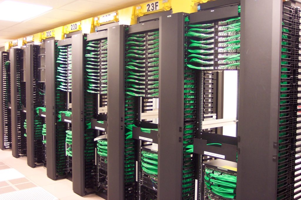
The dramatic growth in data center requires the higher-performance servers, storage and interconnects. From initial 100M, 1G, 10G, to 40G and 100G, high speed Ethernet has never stopped developing. The standard for 10 Gigabit Ethernet (IEEE802.3ae) was ratified in 2002. In 10 Gigabit Ethernet, there are mainly three media: 10G SFP+ transceiver, SFP+ DAC cable and 10GBASE-T SFP transceiver. This post will discuss 10GBASE-T vs SFP+ vs SFP+ cable.

Media Options for 10GbE Network: 10GBASE-T vs SFP+ vs SFP+ Cable

10G SFP+

SFP+ (small form-factor pluggable plus) supports both fibre optic cables and DAC (direct attach cable). It delivers a wide variety of 10GbE Ethernet connectivity options for data center, enterprise wiring closet, and service provider transport applications. But it has the limitations that will prevent the media from moving to every server.

SFP+ Cable

SFP+ cable is designed for 10GbE access layer interconnection in data center. It includes direct attach copper cables and active optical cables. DAC is a lower cost alternative to fibre, but it can support limited transmission distance and it’s not backward-compatible with existing GbE switches. DAC requires the purchase of an adapter card and requires a new top of rack (ToR) switch topology. DAC is more expensive than structured copper channels, and cannot be field terminated.

10GBASE-T SFP

10GBase-T SFP enables 10GbE connections with unshielded or shielded twisted pair cables over distances up to 100 metres. 10GBase-T technology appears as SPF is not compatible with twisted pair cabling system typically used in data centers. With 10GBase-T SFP, the migration from 1GbE to 10GbE can be easily achieved.

10GBASE-T vs SFP+ vs SFP+ Cable

This part will dicuss 10GBASE-T vs SFP+ vs SFP+ Cable from the aspects of latency and power consumption:

Latency

Low latency becomes so important since the adoption of private cloud applications increases. It’s beneficial for ensuring fast response time and reducing CPU (center processing units) idle cycles so that improve data center efficiency.

As to 10GBASE-T SFP, the physical connection (PHY) standard uses block encoding to transport data across the cable without errors. The block encoding requires a block of data to be read into the transmitter PHY, a mathematical function run on the data before the encoded data are sent over the link. It happens the same on the receiver side. This standard specifies 2.6 microseconds for the transmit-receive pair, and the block size requires latency to be less than 2 microseconds. While 10G SFP applies simplified electronics without encoding, and common latency is around 300 nanoseconds per link.

You may think that two microseconds are not high. But what if a TOR infrastructure where traffic is passing 4 hops to reach the destination? 10.4-microsecond delay will be caused when using 10GBASE-T SFP. The following table tells details about the latency of SFP+ cable, 10G SFP and 10GABSE-T SFP for different number of links.

Number of Links SFP+ Cable Latency 10G SFP Latency 10GBASE-T SFP Latency
1 0.3 0.1 2.6
2 0.6 0.2 5.2
3 0.9 0.3 7.8
4 1.2 0.4 10.4
5 1.5 0.5 13.0
6 1.8 0.6 15.6

From the above table, it shows that the latency of 10GBASE-T SFP is the highest. As network links grow, the latency turns to be higher. It’s known that the lower latency, the faster the network speed. High latency in the data center infrastructure results in delays in CPU and application works, therefore limiting data center efficiency and increasing operational costs.

Power Consumption

Power consumption is also one of the important factors to be considered in data centers. Engineers are sensitive to power consumption and find a way to seek the lowest possible power consumption technologies. It’s said that every watt of power consumed, typically two additional watts are needed for cooling.

10GBase-T components today require anywhere from 2 to 5 watts per port at each end of the cable depending on the distance of the cable. But 10G SFP requires about 0.7 watt regardless of distance. The figure below compares the power consumption of three media options of 10GbE Ethernet.

10GBASE-T vs SFP+ vs SFP+ Cable

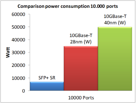
From this figure, suppose there are 10000 ports in the data center, 10G SFP can greatly save the power. On contrary, 10GBASE-T components consumes the most power. Thus, to save power in the data center, 10G SFP and SFP+ cable should better be selected when deploying thousands of cables in a data center.

Conclusion

From this article, 10G SFP+ and SFP+ cable solutions are better than 10GBASE-T SFP for 10G data center. But 10GbE is not the ultimate goal. Besides factors mentioned in this article, you should also select a cabling solution which can support not only current needs but also future data center deployments when you design 10GbE network. You can find various SFP+ modules and 40G QSFP+ from FS.COM.

Related article: How to Convert SFP+ to 10GBASE-T/RJ45?

Dos & Don’ts of Cable Management

Just imagine how would you feel when you face cable spaghetti? You must say, “oh, it’s very annoying.” Yes, that’s right. Improper cable management can bring disadvantages like heat retention, untimely hardware failure, and maintenance headaches. So how to avoid cable spaghetti and keep network cabling in a good organization?

cable management

Since cable management is one of the most important factors of data centre design, it’s necessary to master some cabling skills. The following content will give you some suggestions for cabling installation.

Don’t Pull Fibre Jumpers too Hard

When installing cables, pulling issue can’t be avoided. Pulling cables too hard can damage them by stressing the core. Stressing the core will affect the signal performance. In extreme cases, it will cause unwinding of the twists in the sheath. Under this situation, you should better buy high-quality patch cords from reliable manufacturers or vendors. Good optical fibre is able to withstand the stress. Because cheap cables have sub-standard sheathing and narrow diameter cores which can cause signal loss. A smaller core is also more fragile and weak, more likely to bend, leading to an increased rate of cable failure.

Don’t Ignore Labels

Cable labels are very likely to be ignored by engineers. After finishing cable installation, they always think they can remember every cable type, including the network cables, power cables, patch cables, etc. Things don’t happen like you wish. Your memory will disappear as time goes on. Thus, you should not overlook labeling which can help you identify cables in a short time and leave messages to other installers to easily decipher what goes back.

cable label

Don’t Forget Cable Ties

Cable ties are cheap and useful to get a clean look of your data centre. Today there are many categories in different sizes with many colours. Nylon and Velcro ties are the most two common kinds. Velcro ties are better than plastic ties because they are easy and quick to add, remove and reusable. Nylon cable ties can put much stress on cable bundles and cause pressure points on the cable jacket, changing the cable geometry and thus decreasing performance. What’s more, Velcro ties can be cut easily to any length you need.

Measure the Exact Cable Length You Need

Usually, it says the longer, the better. But it’s another case for network cabling. Improper cable length often causes cable mess. Suppose you have bought 50m patch cable. However, you just use 20m. Then how to deal with the spare 30m cable? Just leave it alone? Of course not. So you’re advised to measure the exact cable length you need. Custom cable is the best solution for you to get the right length.

Leave Space for Cables Trays

What if very long cables are left in your network system? You may consider putting the cables into the cable trays. But it’s not a good idea. Cable trays should not be overloaded. Suspended cable trays are mounted to a rack or something. If it’s too heavy, the cable trays may fall off and break other expensive things. Too many cables are not only safety problem, but also leads to poor operational practices because it’s too hard or fear of disturbing cables. What’s worse, the cables at the bottom of cable try may be crushed and degrade signal propagation.

Choose a Proper Cable Manager

Cable manager is an economical and efficient solution to manage high density structured cabling in data centres and telecommunication rooms, which allows the maximum amount of cables to be organized in a minimum amount of space. Choose the best cable manager which suits the most for your application. Simple or complex cable manager, vertical or horizontal, plastic or metal, one must meet your requirements for network cable management improvement.

cable manager

Conclusion

Cable management is not an easy work. Some engineers may not take cable management seriously or they don’t care much if there is a little mess. But the improper operation can cause lots of problems. To achieve neat cabling, too many things must be taken into consideration. And some useful tools and equipment are also required. Come to find a perfect cabling solution in FS.COM.

Related article: Fiber Patch Panel for High Density Data Center

Comparison Between FBT and PLC Splitters

Enabling a single fibre interface to be shared among many subscribers, fibre optic splitters play an increasingly significant role in many of today’s optical networks. From FTTx systems to traditional optical networks, splitters provide capabilities that help users maximise the functionality of optical network circuits. In this article, I’d like to give a short introduction of fibre optic splitters.

Overview of FBT and PLC Splitters

In simple terms, a fibre optical splitter is a passive optical device that can split, or separate beams into two or more light beams. Based on the configuration of the splitter, these beams may or may not have the equal optical power as the original beam. By means of different constructions, the outputs of a splitter can have varying degrees of throughput, which is highly beneficial when designing optical networks.

fiber optic splitter

Now although technology continually evolves, and there are a variety of existing splitters in the market, the most two common types of fibre optic splitter are: fused biconic tapered splitter (FBT Splitter) and planar lightwave circuit splitter (PLC Splitter).

FBT is the traditional technology in which two fibres are placed closely together and fused together by applying heat while the assembly is being elongated and tapered. As the technology continues developing, the quality of FBT splitter is very good and they can be applied in a cost-effective way. Now FBT is designed to split power in optical telecommunication and widely used in passive networks, especially where the split configuration is relatively small.

FBT splitter.jpg

PLC splitter is a better choice for application where large split configurations are required. It uses an optical splitter chip to divide the incoming signal into multiple outputs. PLC splitter composes of three layers: a substrate, a waveguide, and a lid. The waveguide plays a key role in the splittering process which allows for passing specific percentages of light. Therefore, PLC splitters offer very accurate splits and a low loss. What’s more, PLC splitters have several types such as bare PLC splitter, blockless PLC splitters, fanout PLC splitter, mini-plug in type PLC splitter, etc.

PLC splitter.jpg

With the growth of FTTx worldwide, in order to serve mass subscribers, the demand for large split configurations in these networks has also grown quickly. Because of the performance benefits and overall low cost, PLC splitters are now the better solutions for these types of applications.

FBT Splitter vs. PLC Splitter

In optical networks, signals need to be splitted somewhere in order to serve for different customers. Splitter technology has made great progress in the past few years by introducing PLC splitter. However, being similar in size and outer appearance, the two types of splitter still have many differences. Here is a brief comparison of them.

Materials

FBT splitter is made out of materials that are easily available, for example, steel, fibre, hot dorm and others. All of these materials are cheap, which determines the low cost of the device itself. The technology of the device manufacturing is also relatively simple, which leads to its low prices as well. Compared with FBT splitters, the technology of PLC splitter is more complicated and expensive. It uses semiconductor technology production. Hence it is more difficult to manufacture PLC splitters. And the price of the device is higher.

Operating Wavelength

FBT splitters only supports three wavelengths: 850 nm, 1310 nm and 1550 nm, which makes its inability to works on other wavelengths. While PLC splitter can support wavelength from 1260 to 1650 nm. The adjustable rang of wavelength allows PLC splitter more wide applications.

Split Ratio

The split ratio of FBT splitter is up to 1:32, while the ratio PLC splitter goes up to 64, providing a high reliability. Furthermore, the signal in PlC splitter can be split equally due to technology implemented.

Temperature

In certain areas, temperature can be a crucial factor that affects the performance of optical components. Therefore, sometimes devices with good cold resistance is also vital. FBT splitter can work stable under the temperature of -5 to 75℃. PLC splitter can work at a wider temperature range of -40 to 85 ℃, providing relatively good performance in the areas of extreme climate.

Apart from the differences mentioned above, there are still other differences between FBT splitter and PLC splitter. For example, compared with FBT splitter, the size of PLC splitter is more compact. Hence, PLC spitter is more suitable for density applications.

Conclusion

In conclusion, this article introduce the fibre optical splitters and the differences between FBT splitter and PLC splitter. It’s significant to choose the most suitable splitters for your networks. There are a variety of splitters avaible in Fiberstore. If you want to know detailed information, please visit FS.COM.

Fibre Patch Panel for High Density Data Centre

Fibre optic cable has been increasingly applied to meet the need of high speed network. In data centres, the cabling infrastructure turns to be more complicated. Under that situation, keeping good cable management is necessary since messy cabling will cause fibre optic loss and not easy for troubleshooting. Then fibre patch panels can serve as the tools for cabling systems.

Fiber-Patch-Panel

A fibre patch panel is also called fibre distribution panel. It’s used to terminate the fibre optic cable and provide connection to individual spliced fibres. Besides, fibre patch panels can create a secure environment for exposed fibres, housing connectors and splice unites.

Fibre Patch Panel Types

Fibre patch panels can be divided into two types. Both types can house, organise, manage and protect fibre optic cable, splices and connectors.

One is rack mount enclosure. Usually the rack mount enclosure holds the fibres horizontally and looks like a drawer. Rack mount enclosure is designed in 1U, 2U, 4U sizes and can hold up to 288 or even more fibres. The rack mount enclosures include two kinds. One is the slide-out variety and the other incorporates a removable lid. The sliding design of panels gives engineer easy access to the fibres inside but it’s more expensive. The lid type is less expensive but requires the user to remove the whole enclosure from the rack to gain internal access.

The other is wall mount enclosure. While wall mount enclosure is designed for enclosed wall mounting of adapter panels or splice trays. They are fabricated from steel sheets and finished with a light textured black powder coat. These panels can be easily mounted to any wall using the internal mounting holes. They can protect fibres from dust or debris contamination and organise the cables.

 wall-mount

Fibre Patch Panel Structure

A typical fibre patch panel contains four parts: enclosed chamber (rack mount or wall mount), adapter panels, connector adapters (providing low optical loss connection through mating appropriate connectors) and splice tray (organizing and securing splice modules). Adapters on a fibre patch panel are available in different shapes, such as LC, SC, MTP, etc. Most times, all adapters are of the same type in a panel. But sometimes a panel with different types of adapters is needed when more than one type of fibre optic connectors used in a network.

Fibre patch panel has two compartments. One contains the bulkhead receptacles or adapters, and the other is used for splice tray and excess fibre storage. Patch cable management trays are optional for some patch panels and make possible the neat storage of excessive patch cable lengths.

Fibre Patch Panel Ports

Fibre patch panel ports provide a place for data to enter and exit the panel. The number of these ports vary from 12, 24, 48, 64, 72, 96 to 288 and even more. Actually there is no limit to the number of ports on a patch panel. As long as there is enough room, you can fill the enclosure without interfering with the integrity.

FS.COM offers a 288 fibres 4RU rack mount fibre optic enclosure, loaded with 12 slots duplex fibre adapter panels. This high density patch panel provides a flexible and modular systems for managing fibre terminations, connections, and patching in all applications. With its high fibre densities and port counts, it maximises rack space utilization and minimises floor space. This enclosure makes it easy for network deployment, moves, adds, and changes. It’s a perfect solution for engineers to do the fibre termination and distribution.

288-fiber enclosure

Fibre Termination in the Patch Panel

In a patch panel, pigtail or field termination can be used for the connection. If it uses the pigtail approach, a splice tray is needed in the patch panel. This method provide the best quality connection and is usually the quickest. The second method uses fibre optic connector for field termination. A fibre optic connector is directly installed onto the individual fibres. This method usually takes longer time than pigtail but doesn’t need a splice tray in the patch panel. However, the connection quality may not be as good as pre-terminated pigtails.

Summary

Fibre patch panels are very useful especially in the high density data centre. They feature with the benefits of easy fibre installation, maximum flexibility and manageability. Although patch panels are attractive, it’s the best only when it fits your application. No matter rack mount or wall mount type, loaded or unloaded, you should better choose the most suitable one based on your own situation.

Related article: Dos & Don’ts of Cable Management

Guide to Choose the Right Fiber Optic Patch Cable

Now with the fibr eoptic cable being widely used in a variety of industries and places, the requests for fibre patch are being elaborated. Fibre patch cables are being required to be improved and provided more possibilities to satisfy various application environments. Actually, many special fibre patch cables have been created to answer the market demand. But do you know how to choose right fibre optic patch cable for our network system? The following passages may give you a clear guideline to choose the suitable patch cables.

Why You Need Different Fibre Optic Patch Cables?

Fibre optic patch cable, some times also called fibre optic jumper cable, are terminated with fibre optic connectors on both ends. Due to the fact that fibre patch cable can carry more data efficiently, they play an important role in telecommunication and computer networking. And they are also used in numbers of places. Therefore, when you choose fibre patch cables, the first thing you need to know is the environment that the patch cable will be used. Indoor or outdoor? In the air or buried underground? Different environments have different requirements for cables. Let’s take armored fibre patch cable for example. Armored fiber patch cable, wrapped a layer of protective “armor” outside of the fibre optic cable, is generally adopted in direct buried outside plant applications where a rugged cable is needed for rodent resistance.

fibre optic patch cables

What You Should Concern to Choose the Fibre Optic Patch Cable?
Single-mode vs Multimode

Single-mode fibre patch cable uses 9/125um glass fibre and multimode fiber patch cable uses 50/125um or 62.5/125um glass fiber. Generally, single-mode fiber patch cables are the best choice for transmitting data over long distances. They are usually used for connections over large areas, such as college campuses and cable television networks. And most single-mode cabling is color-coded yellow. Multmode fibre patch cables are usually used in short distances. They are typically used for data and audio/visual applications in local-area networks and connections within buildings. Multimode cables are generally color-coded orange or aqua.

Simplex vs Duplex

Simplex Fibre optic cable means the cable composes of only one fibre, then a duplex patch cable consists of two fibres. Therefore, simplex fibre optic cable is common used in a system where only one-way data transfers. And duplex fibre optic cable is applied to where requires simultaneous, bi-directional data transfer.

Connector Types

On both ends of the fibre optic patch cable are terminated with a fibre optic connector (LC/SC/ST/FC/MPO/MTP). With the rapid development of optical fibre telecommunication, many different types of fiber connectors are available. They share similar design characteristics. Different connector is used to plug into different device. If ports on the both ends devices are the same, the patch cables such as LC-LC/SC-SC/MPO-MPO can be used; if you want to connect different ports type devices, LC-SC, LC-FC and LC-ST patch cables may meet your demand.

Polishing Types

It’s known to us that whenever a connector is installed on the end of fibre, loss cannot be avoided. Some of this light loss is reflected directly back down the fibre towards the light source that generated it. These back reflections will damage the laser light sources and also disrupt the transmitted signal. In order to optimise transmitting performance and ensure the proper optical propagation, the end of the fibre must be properly polished to minimize loss. Generally, there are two common polishing types: UPC and APC. And the loss of APC connector is lower than UPC connectors. So the optical performance of APC connector is better than UPC connectors.

Cable Jacket

The cable jacket is to provide strength, integrity, and overall protection of the fibre member. When choose one kind of fibre optic cables, the environment that the cables be used should be taken into consideration. Usually there are three types of jacket: PVC, LSZH and OFNP. Which one you choose depends on where you use the cables. Here are their features.

  • PVC cable resistant to oxidation, it is commonly used for horizontal runs from the wiring centre.
  • LSZH cable has a special flame-retardant coating and it is used between floors in a building.
  • OFNP cable has fire-resistance and low smoke production characteristics. It usually works for vertical runs between floors.
Conclusion

In summary, there are many factors which may affect your choices of fibre optic patch cable. So it’s important to make sense which kind of patch cable can really meet your requirements. FS can provide all kinds of fibre optic patch cables to satisfy your needs!

To approve a single suggestion, mouse over it and click “✔”
Click the bubble to approve all of its suggestions.

LC Connector for High Density Data Centres

SC duplex connector was popular a few years ago. But as time goes on, smaller and more compact cabling components are required since the packing density of optical devices keeps increasing, namely high density. The smaller the shape, the more popular the component, just like development history of cellphone. Driven by this requirement, optic manufacturers start to produce mini components. The most widely known is the LC connector, a small form factor connector. The following article will introduce various types of LC connectors in details.

LC small form factor connector has just 1.25mm ferrule, half the size of the standard connector (compared with SC connector). Because of the high density design, LC connector solution can reduce the space needed on racks, enclosures and panels by approximately 50% throughout the network. So LC connector is a good solution for high density data centres. The LC connector uses RJ45 push-pull style plug that offers a reassuring, audible click when engaged. It makes moves, adds and changes easy and saves costs for you. Besides, the protective cap completely covers the connector end, which prevents ferrule end face from contamination and impact and enhances the network performance.

lc-lc-duplex

LC Uniboot

LC uniboot connector includes a finger latch release that there is no need for tools when making the polarity change. Some LC uniboot connectors are color-coded and labeled “A” and “B” to provide visual references when making a polarity change. The uniboot design is compatible with transceivers using the LC interface. The LC uniboot patch cords use special round cable that allows duplex transmission within a single cable, and it greatly reduces cable congestion in racks and cabinets comparing to standard patch cords. LC uniboot patch cord is perfect for high density applications. FS.COM LC uniboot patch cords are available in SM, OM3 or OM4 multimode fibre types to meet a wide variety of configurations and requirements.

uniboot-lc

Push-Pull LC Connector

If you have tried to release LC connectors in patch panels with high density, you must know how difficult it is. As to high density panel, thumbs and forefingers can not easily access to pull the connector. So some manufacturers start to offer a special LC connector which can be easily dealt with. And that’s push-pull tab LC connector.

Push-Pull-Tab-Patch-Cable

LC push-pull connectors offer the easiest solution for installation and removal. The special design is available in a compact model, ideal for minimizing oversized panels. With this kind of connector, you don’t need to leave additional space at the top or bottom to allow room for engaging the latch. The structure of the LC push-pull compact is designed as the latch can be slid back, instead of being pushed down, to facilitate smooth removal. It’s simple for installation and removal. Push-Pull LC patch cable allows users accessibility in tight areas when deploying LC patch fields in high density data centres. Push-Pull LC fibre patch cords are available in OM4, OM3 or single-mode fibre types to meet the demands of Gigabit Ethernet, 10 Gigabit Ethernet and high speed Fibre Channel.

Secure Keyed LC Connector

Secure keyed LC connectors are designed for network security and stability. 12 colors are available in FS.COM, including red, magenta, pink, yellow, orange, turquoise, brown, olive, etc. Connections only work when the color matches. The color-coded keying options provide design flexibility and facilitate network administration. It reduces risks and increases the security of network from incorrect patching of circuits. Secure keyed LC connectors feature low insertion loss, excellent durability.

lc-keyed

Conclusion

This article tells different types LC connectors, including common LC connector, LC uniboot, push-pull LC and secure keyed LC connector. The design of those LC connectors keeps improving to adapt to high density data centrers. Nowadays, the trend of network is high speed and high density. So effective cable management is significantly important. And the key concern is how to manage more cables within less space. Thus, among so many kinds of interfaces, LC connector is the most frequently used and the most effective solution for space saving in data centres.

Suggestions for Data Centre Design

The demands on data centres and networks are growing very fast. To meet communication needs, more and more devices are connected to the data centre network links. It brings difficulties in data centre management. The infrastructure design should guarantee the reliable network performance. But how to achieve the best performance? Four suggestions are recommended for you when designing a data centre.

Maximizing Network Performance

As today, many companies adopt high density configurations and virtualization to increase the capacity of existing IT equipment. To ensure the network performance, a robust data centre infrastructure is necessary. And three parts of the infrastructure must be considered: the structured cabling, racks and cabinets, and the cable management.

data-center

Figure 1. Structured data centre

First, the structured cabling performance has a close relationship to the connectivity and cable components. If the components fail to deliver good cabling system, great optical loss will be caused. To improve the channel performance, insertion loss should be minimized especially in 40G and 100G data centre. Second, choose right rack or cabinet to accommodate new equipment with different size and weight requirements since active equipment in the infrastructure turn to be broken easily and will be replaced in five years or less. Third, manage the airflow and maintain good cooling system. Because the rising temperature of the data centre has an influence on network performance. The last component of the infrastructure is cable management. A well-designed cable management should meet the standards of spare space, high reliability and scalability. The infrastructure is designed for both copper and fibre, maintaining proper bend radius for both copper and fibre, protecting cable from damage, and creating crosstalk and return loss.

Saving Time

Although data centre grows in size and complexity, it often requires faster deployment. It must adapt to the rapid changing business requirements. As it says, time is money. Selecting an infrastructure that optimize time, result in faster deployments can save lots of costs.

In order to save time in deployment, installation and future moves, adds, and changes, a suitable modular solution based on the rack or cabinet should be applied. The modular solution is also good for effective airflow management and cooling, which can save time because it can easily support high density when needed. Pre-terminated copper and fibre cabling solutions can also save time during installation and future cabling moves. Pre-terminated fibre systems, for example, MPO to MPO trunk cables or MPO to LC harness cables, can facilitate the migration to higher speeds.

Optimizing Spare Space

To adapt to high speed demands, data centre infrastructure turns to be more complex. Now space is a premium in the data centre as port densities continue to increase. Considering the cost, infrastructure should be optimized for greater flexibility and scalability. High density connectivity options including high density patch panel, MTP cassette, etc. are the solutions to optimize space while supporting large port densities. For instance, LC connectors (2 fibre) have been replaced by MPO (typically 12 or 24 fibres) connectors for the migration from 10 GbE to 40 GbE and 100 GbE.

MTP-solution

Figure 2. MTP components for saving space

To optimize space in the data centre, the following factors are needed to be considered:

  • Choose the rack or cabinet as your basic building block
  • Select racks and cabinets with higher weight limits, sufficient depth and heights that support growing vertically
  • Select cable management that can support existing and future cable density, fluent airflow, and is designed to support both copper and fibre
  • Select connectivity that supports high density and mixed media
  • Use cable with small outside diameter
  • Consider patching outside the rack and cabinet to save space for equipment
  • Select a rack or cabinet solution that easily integrates with overhead pathways
Finding a Cooperator With Rich Experience

During the design phase, the data centre design must provide guaranteed performance while providing flexibility and scalability for future needs. During the installation phase, the solution must be easy to install, quick to deploy and easy to manage. So it’s important to find a qualified contractor who has a history of quality installations. You also need to choose a good manufacturer providing cost-effective components covering cooling, power, connectivity, cabling, racks and cabinets, cable management, and pathways, like Fiberstore (FS.COM). And the manufacturer should also have expertise of extending the equipment life, reducing cost and solving other problems in the data centre.

Summary

Data centre design is not an easy job as the cabling infrastructure becomes more complex for meeting the growing high data rates demands. To maximize the efficiency of a data centre, too many elements should be taken into consideration. The above content gives suggestions for data centre design to guarantee performance, save time, optimize space, and find an experienced cooperator. Hope this article is useful to your data centre design.