
In fibre optical networks passive components such as optical isolators are essential for delivering of signals with minimum loss. Another type of passive element that is commonly used in fibre optic systems is the optical circulator. These devices that are used to direct the optical signal from one port to another port and in one direction only. This action prevents the signal from propagating in an unintended direction. Optical circulators have continued to increase their presence in a broad array of applications, including optical amplifiers, optical add and drop systems, dense wavelength-division multiplexing (DWDM Mux) networks and, optical time domain reflectometers (OTDRs).
In a 3-port circulator a signal is transmitted from port 1 to port 2, another signal is transmitted from port 2 to port 3 and, finally, a third signal can be transmitted from port 3 to port 1. This behavior is represented by the following.
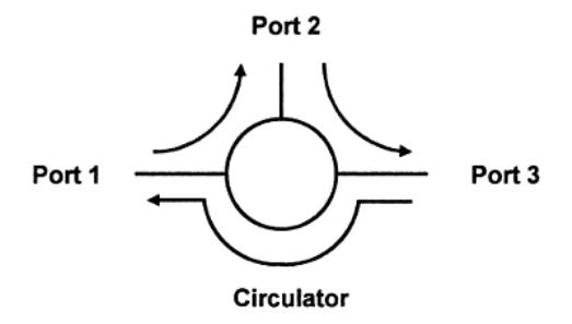
Figure 1 Conventional figure to represent the behavior of an optical circulator.
The name derives from the fact that a signal is transmitted from Port 1 to Port 2, another signal can be transmitted from Port 2 to Port 3 and, finally, a signal can be transmitted from Port 3 to Port 1. In practice, one or two ports are used as inputs and the third port is used as the output.
Two simple examples of optical circulators can be considered. The first is an EDFA amplifier (erbium doped fibre amplifier) application to amplify a signal. The configuration to do this with a three-port optical circulator is shown in the following figure.
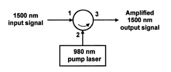
Figure 2. Amplification of an input optical signal by a pump laser.
In the figure, a weak optical signal at 1550nm is input to Port 1 and is directed to Port 2. The weak signal at Port 2 is pumped by a 980nm pump lasers and the amplified signal is then transmitted from port 2 to the output Port 3.
In the second example, we consider the application of a Fibre-Bragg grating compensator to correct a distorted signal. This can also be done using a three-port optical circulator as shown in the following figure.
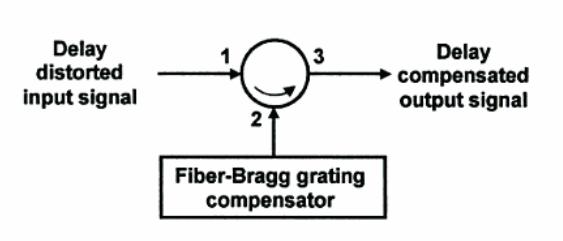
Figure 3. Fibre dispersion compensation of a distorted signal.
In the figure the distorted signal at Port 1 is conditioned by transmitting the delay distorted input signal to the input of Port 2. At Port 2 dispersion compensation is applied and the compensated (corrected) signal is transmitted to Port 3.
We now analyze the operation of the three-port optical circulator. We begin by considering the figure shown below.
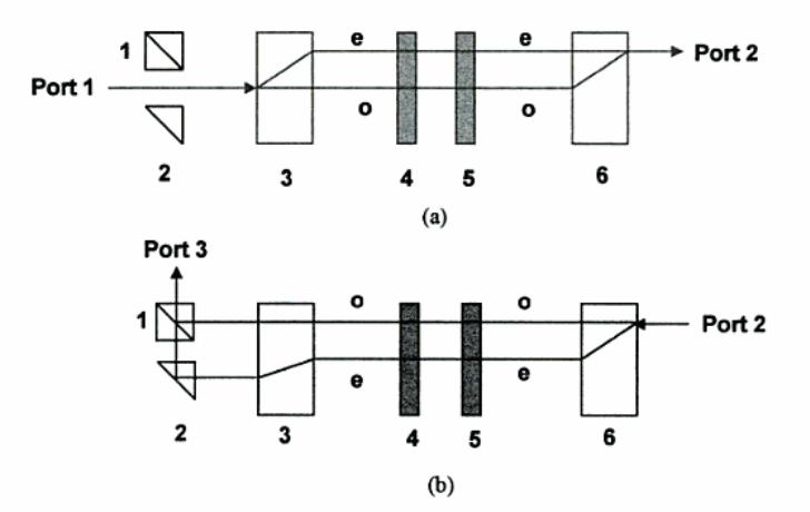
Figure 4. Configuration of a three-port optical circulator.
The components are a beam splitting polarizer (1), a reflection prism (2), two birefringent crystals (3,6), a Faraday rotator (4), and a half-waveplate (5). The upper figure (a) describes the propagation from Port 1 to Port 2 and lower figure (b) describes the propagation from Port 2 to Port 3.
Optical circulators can be used to achieve bi-directional optical signal transmission over a single fibre. Optical circulators is commonly used in WDM networks, polarization mode dispersion, chromatic dispersion compensation, optical add-drop modules (DWDM OADM), optical amplifiers, OTDR and fibre sensing applications. Fiberstore offer 3/4 ports polarization-insensitive optical circulator and 1310/1550/1064 polarization-maintaining (PM) optic circulators. Our fibre optical circulators can provide high isolation, very low insertion loss, low polarization dependent loss (PDL), low polarization mode dispersion (PMD), and excellent environmental stability. Any other wavelengths, without or with any connector can customised according to your requirement.
Related Article: STP vs. UTP, Which One Is Better?