
LINKSYS, a division of Cisco Systems. Linksys SFP module includes mgblh1, mgbt1, mgbsx1, etc. This paper tells us how to use these Linksys SFP modules.
Tips: The Linksys company was founded in 1988. It is currently owned by Belkin, who bought it from Cisco, its owners from March 2003 to March 2013. Its products were branded as Linksys by Cisco when it was part of Cisco.
Description of MFE and MGE SFP Transceiver Modules
MFE Transceivers
- MFELX1 100BASE-LX SFP transceiver, for single-mode fibre, 1310 nm wavelength, support up to 10 km, with Duplex LC connector
- MFEFX1 100BASE-FX SFP transceiver, for multimode fibre, 1310 nm wavelength, support up to 2 km, with Duplex LC connector
- MFEBX1 100BASE-BX-20U SFP transceiver for single-mode fibre, 1310 nm wavelength, support up to 20 km, with Single LC connector
MGE Transceivers
- MGBT1 1000BASE-T SFP transceiver for category 5 copper wire, support up to 100 m, with RJ45 connector
- MGBSX1 1000BASE-SX SFP transceiver, for multimode fibre, 850nm wavelength, support up to 550 m, with Duplex LC connector
- MGBLX1 1000BASE-LX SFP transceiver, for single-mode fibre, 1310 nm wavelength, support up to 10 km, with Duplex LC connector
- MGBLH1 1000BASE-LH SFP transceiver, for single-mode fibre, 1310 nm wavelength, support up to 40 km, with Duplex LC connector
- MGBBX1 1000BASE-BX-20U SFP transceiver, for single-mode fibre, 1310 nm wavelength, support up to 20 km, with Single Lc connector
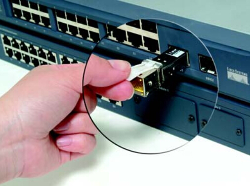
These Modules insert into the mini-GBIC ports on either the SR2024 or SR224G, creating new Gigabit ports. Each Gigabit SFP Module is h ot-swappable, meaning you can connect them even when the switch is running. Use the following directions for inst alling and removing either the MGBLH1 and MGBSX1 or the MGBT1.
Installation and Removal Directions for the MGBLH1 and MGBSX1
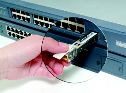
1. Insert the Gigabit SFP Module with the printed side up and the rubber port cap facing out.
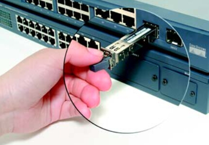
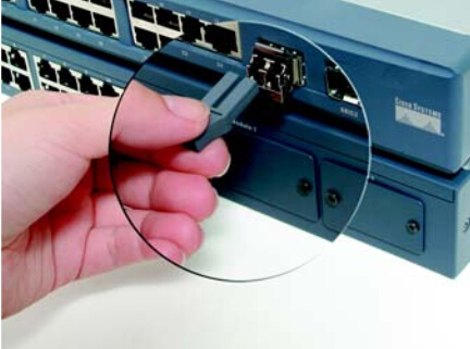
2. Remove the Gigabit SFP Module’s rubber port cap.
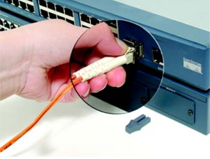
3. Connect the fibre cable’s LC Con- nector to the Gigabit SFP Module’s port.
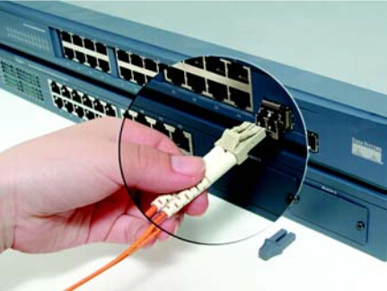
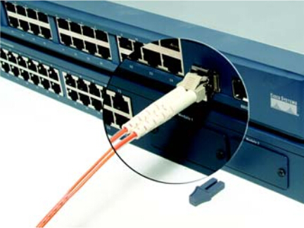
4. Now the fibre is connected to the Gigabit SFP Module and should be functioning. Connect the other end of the cable to an SFP Module to verify that the fibre connection is complete.
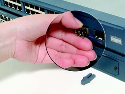
5. Press the fibre cable’s connector and pull to remove the fibre cable from the Gigabit SFP Module.
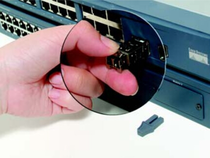
6. To remove the Gigabit SFP Module, begin by pulling the Module’s bail latch.
7. Now, remove the Gigabit SFP Module.
Installation and Removal Directions for the MGBT1
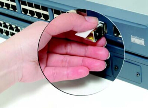
1. Insert the Gigabit SFP Mod- ule with the printed side up and the pull tab facing out.
2. Lock the Gigabit SFP Module in place.
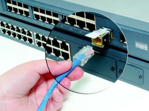
3. Connect the Cat5 cable to the Gigabit SFP Module’s port. Connect the other end of the Cat5 cable to another switch that is equipped with a Link- sys MGBT1 or Gigabit Ethernet port.
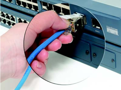
4. Press the RJ-45 connector’s tab and pull to remove the Cat5 cable from the Gigabit SFP Module.
5. To remove the Gigabit SFP Module, begin by pulling the Module’s pull tab.
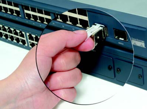
6. Now, remove the Gigabit SFP Module.
For more information on optical transceivers, read What Is An Optical Module?
Related Article: