Tag Archives: LC connector

FS Polarity Switchable LC Uniboot Cable: Leading Trend in Fibre Optics

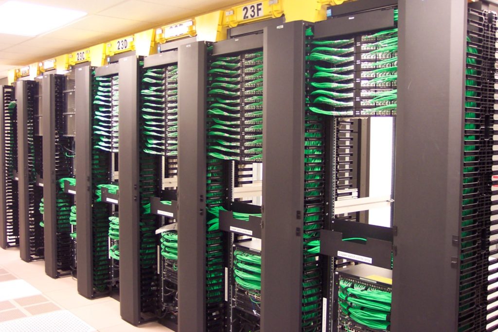
The data centre is moving towards high speed and high density. How to build more optical fibre cables in limited space is becoming increasingly severe. In this case, FS.COM introduced a new-type product suitable for high density cabling requirement—polarity switchable LC uniboot cable. It’s the preferred option for high density data centre connection today. Its largest feature is switchable polarity, designed to eliminate the need for dual zip cords and reduce overall bulk cabling by 50%. But do you know about polarity switchable LC uniboot cable? What are the features of it and how to reverse the polarity? You may find answer in this post.

Introduction to LC Uniboot Fibre Patch Cable

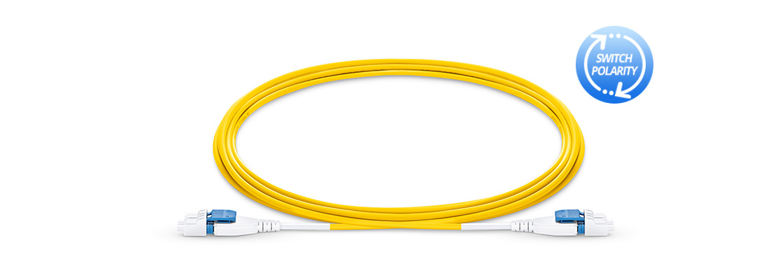
LC uniboot fibre patch cables are designed for high density applications in data centre environment. Generally, the LC uniboot patch cord is designed with a polarization method that can help users easily reverse the fibre polarity. In addition, the LC uniboot fibre patch cable can reduce cable management space comparing to standard patch cord as it places both simplex fibres into one jacket while still terminating into a duplex LC connector. Similar to the standard patch cord, single-mode and multimode versions are available in LC uniboot patch cables.

Polarity Switchable LC Uniboot Cable

Features & Advantages

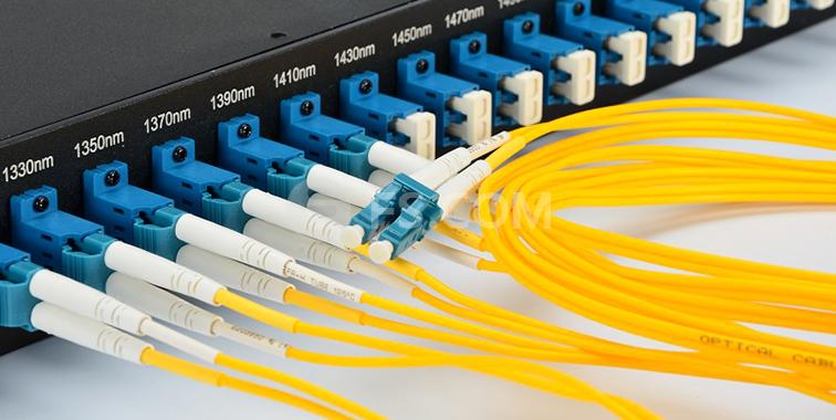
FS polarity switchable LC uniboot cables feature high density. They are used to connect switches or network devices in fibre networks directly or interconnect structured cabling systems in a fibre network. Besides, FS uniboot fibre patch cable has the following highlights.

  • Easy polarity reversal: Polarity changes can be made in the field quickly, without the use of tools, to the correct fibre mapping polarity.
  • “All in One” international quality cable assemblies: FS uniboot fibre patch cable has passed IEC61300-3-35 end-face standard, EIA/TIA-455-171A attenuation standard and CE, etc. providing customers with the outstanding, standards-compliant products and services.
  • LC licence compliant & 0.2dB IL: The worldwide licence and low insertion loss keep your network running fast and smooth.
  • 2.0mm round cable design: 2.0mm thin diametre allows the polarity to be switched from A-B to A-A without any tools.
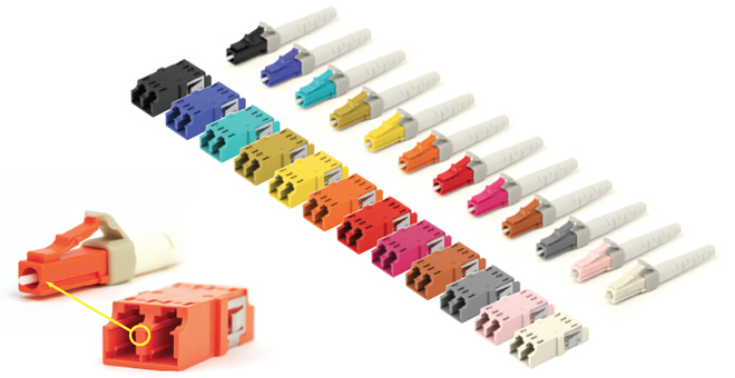
  • More fibre options: OM3, OM4, and OS2.
  • Space saving: It can save the space of cassettes and cable management by 68%.
How to Achieve Polarity Reversal of LC Uniboot Cable

As we know, for traditional cabling systems using single fibre connectors, maintaining polarity requires that the “A” transmits signal and at the same time the “B” receives signal. But duplex patch cords used to complete serial duplex pair connections available in two types, depending on which polarity technique is used— “A-to-B” patch cord for “straight-through” wiring and “A-to-A” patch cord for “crossover”wiring. Thus, polarity reversal is usually required during fibre optic cabling.

However, polarity reversal of traditional LC patch cable is very inconvenient and annoying since some minor mistakes could lead to various troubles. Therefore, FS.COM developed the LC uniboot cable that is easier for polarity reversal, without having to re-terminate the connectors. Here two methods of polarity reversal are introduced as follows.

LC-uniboot-polarity-reversal

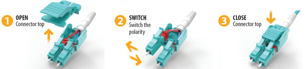
From the above picture, we can see that we can use just 3 steps to reverse polarity. Type one (the left one):

1. Open connector top.

2. Switch the polarity from A-B to A-A.

3. Close connector top.

Type two (the right one):

1. Open connector top.

2. Rotate connector 180 degree to exchange the position.

3. Close connector top.

Summary

To address the increasing demand for high density applications and smaller fibre cable, the LC uniboot fibre patch cable is designed to help cut down cabling space and provide more effective polarity reversal solution. I hope this article could help you choose the proper product for high density cabling. FS.COM not only provides polarity switchable LC fibre patch cable, but also provides bend insensitive fibre patch cable which is also a high density cabling application. Welcome to consult with customer service for more details.

LC Connector for High Density Data Centres

SC duplex connector was popular a few years ago. But as time goes on, smaller and more compact cabling components are required since the packing density of optical devices keeps increasing, namely high density. The smaller the shape, the more popular the component, just like development history of cellphone. Driven by this requirement, optic manufacturers start to produce mini components. The most widely known is the LC connector, a small form factor connector. The following article will introduce various types of LC connectors in details.

LC small form factor connector has just 1.25mm ferrule, half the size of the standard connector (compared with SC connector). Because of the high density design, LC connector solution can reduce the space needed on racks, enclosures and panels by approximately 50% throughout the network. So LC connector is a good solution for high density data centres. The LC connector uses RJ45 push-pull style plug that offers a reassuring, audible click when engaged. It makes moves, adds and changes easy and saves costs for you. Besides, the protective cap completely covers the connector end, which prevents ferrule end face from contamination and impact and enhances the network performance.

lc-lc-duplex

LC Uniboot

LC uniboot connector includes a finger latch release that there is no need for tools when making the polarity change. Some LC uniboot connectors are color-coded and labeled “A” and “B” to provide visual references when making a polarity change. The uniboot design is compatible with transceivers using the LC interface. The LC uniboot patch cords use special round cable that allows duplex transmission within a single cable, and it greatly reduces cable congestion in racks and cabinets comparing to standard patch cords. LC uniboot patch cord is perfect for high density applications. FS.COM LC uniboot patch cords are available in SM, OM3 or OM4 multimode fibre types to meet a wide variety of configurations and requirements.

uniboot-lc

Push-Pull LC Connector

If you have tried to release LC connectors in patch panels with high density, you must know how difficult it is. As to high density panel, thumbs and forefingers can not easily access to pull the connector. So some manufacturers start to offer a special LC connector which can be easily dealt with. And that’s push-pull tab LC connector.

Push-Pull-Tab-Patch-Cable

LC push-pull connectors offer the easiest solution for installation and removal. The special design is available in a compact model, ideal for minimizing oversized panels. With this kind of connector, you don’t need to leave additional space at the top or bottom to allow room for engaging the latch. The structure of the LC push-pull compact is designed as the latch can be slid back, instead of being pushed down, to facilitate smooth removal. It’s simple for installation and removal. Push-Pull LC patch cable allows users accessibility in tight areas when deploying LC patch fields in high density data centres. Push-Pull LC fibre patch cords are available in OM4, OM3 or single-mode fibre types to meet the demands of Gigabit Ethernet, 10 Gigabit Ethernet and high speed Fibre Channel.

Secure Keyed LC Connector

Secure keyed LC connectors are designed for network security and stability. 12 colors are available in FS.COM, including red, magenta, pink, yellow, orange, turquoise, brown, olive, etc. Connections only work when the color matches. The color-coded keying options provide design flexibility and facilitate network administration. It reduces risks and increases the security of network from incorrect patching of circuits. Secure keyed LC connectors feature low insertion loss, excellent durability.

lc-keyed

Conclusion

This article tells different types LC connectors, including common LC connector, LC uniboot, push-pull LC and secure keyed LC connector. The design of those LC connectors keeps improving to adapt to high density data centrers. Nowadays, the trend of network is high speed and high density. So effective cable management is significantly important. And the key concern is how to manage more cables within less space. Thus, among so many kinds of interfaces, LC connector is the most frequently used and the most effective solution for space saving in data centres.

Suggestions for Data Centre Design

The demands on data centres and networks are growing very fast. To meet communication needs, more and more devices are connected to the data centre network links. It brings difficulties in data centre management. The infrastructure design should guarantee the reliable network performance. But how to achieve the best performance? Four suggestions are recommended for you when designing a data centre.

Maximizing Network Performance

As today, many companies adopt high density configurations and virtualization to increase the capacity of existing IT equipment. To ensure the network performance, a robust data centre infrastructure is necessary. And three parts of the infrastructure must be considered: the structured cabling, racks and cabinets, and the cable management.

data-center

Figure 1. Structured data centre

First, the structured cabling performance has a close relationship to the connectivity and cable components. If the components fail to deliver good cabling system, great optical loss will be caused. To improve the channel performance, insertion loss should be minimized especially in 40G and 100G data centre. Second, choose right rack or cabinet to accommodate new equipment with different size and weight requirements since active equipment in the infrastructure turn to be broken easily and will be replaced in five years or less. Third, manage the airflow and maintain good cooling system. Because the rising temperature of the data centre has an influence on network performance. The last component of the infrastructure is cable management. A well-designed cable management should meet the standards of spare space, high reliability and scalability. The infrastructure is designed for both copper and fibre, maintaining proper bend radius for both copper and fibre, protecting cable from damage, and creating crosstalk and return loss.

Saving Time

Although data centre grows in size and complexity, it often requires faster deployment. It must adapt to the rapid changing business requirements. As it says, time is money. Selecting an infrastructure that optimize time, result in faster deployments can save lots of costs.

In order to save time in deployment, installation and future moves, adds, and changes, a suitable modular solution based on the rack or cabinet should be applied. The modular solution is also good for effective airflow management and cooling, which can save time because it can easily support high density when needed. Pre-terminated copper and fibre cabling solutions can also save time during installation and future cabling moves. Pre-terminated fibre systems, for example, MPO to MPO trunk cables or MPO to LC harness cables, can facilitate the migration to higher speeds.

Optimizing Spare Space

To adapt to high speed demands, data centre infrastructure turns to be more complex. Now space is a premium in the data centre as port densities continue to increase. Considering the cost, infrastructure should be optimized for greater flexibility and scalability. High density connectivity options including high density patch panel, MTP cassette, etc. are the solutions to optimize space while supporting large port densities. For instance, LC connectors (2 fibre) have been replaced by MPO (typically 12 or 24 fibres) connectors for the migration from 10 GbE to 40 GbE and 100 GbE.

MTP-solution

Figure 2. MTP components for saving space

To optimize space in the data centre, the following factors are needed to be considered:

  • Choose the rack or cabinet as your basic building block
  • Select racks and cabinets with higher weight limits, sufficient depth and heights that support growing vertically
  • Select cable management that can support existing and future cable density, fluent airflow, and is designed to support both copper and fibre
  • Select connectivity that supports high density and mixed media
  • Use cable with small outside diameter
  • Consider patching outside the rack and cabinet to save space for equipment
  • Select a rack or cabinet solution that easily integrates with overhead pathways
Finding a Cooperator With Rich Experience

During the design phase, the data centre design must provide guaranteed performance while providing flexibility and scalability for future needs. During the installation phase, the solution must be easy to install, quick to deploy and easy to manage. So it’s important to find a qualified contractor who has a history of quality installations. You also need to choose a good manufacturer providing cost-effective components covering cooling, power, connectivity, cabling, racks and cabinets, cable management, and pathways, like Fiberstore (FS.COM). And the manufacturer should also have expertise of extending the equipment life, reducing cost and solving other problems in the data centre.

Summary

Data centre design is not an easy job as the cabling infrastructure becomes more complex for meeting the growing high data rates demands. To maximize the efficiency of a data centre, too many elements should be taken into consideration. The above content gives suggestions for data centre design to guarantee performance, save time, optimize space, and find an experienced cooperator. Hope this article is useful to your data centre design.

MPO Cables Testing Method

As the migration to 40G/100G Ethernet using parallel array transmission systems, the high-density MPO cables are widely used in the data centre. In the connection, contamination even as small as 0.001 mm can cause the optical loss. Mating a contaminated connector to a clean connector will lead to poor performance and can damage the connection. So it’s important to test the link segments consisting of MPO array cabling and keep the cable clean. However, MPO cable testing and cleaning is full of challenges.

Why MPO cable testing and cleaning is not easy? First, MPO connectors are very sensitive to dirt and contamination. The ferrules are large and hard to clean and inspect. Most microscopes don’t have adapters for MPO connectors. Those microscopes with adapters for MPO connectors can only see a small section of the ferrule because they are adapted from single fibre microscopes. So you have to inspect the entire ferrule and every fibre. Second, cleaning is also a problem because of the designs of MPO connectors with pins and holes. Most dry cleaners can only clean the place between the pins. However, dirt may accumulate around the pins or in the holes, which cause alignment problems. So remember to keep MPO connectors well covered and protected when not in use.

Calculate the Acceptable Attenuation

Calculate the acceptable total loss of the entire optical link so that you can find if the test result is good or bad. Do as the following steps with your link loss calculator:

  • 1. Select the fibre type and test wavelength combination;
  • 2. Select the unit of length in feet or meters;
  • 3. Enter the total link length under test;
  • 4. Enter the number of connections of each type (a pair of connectors counts as one connection);
  • 5. Enter the number of splices (each connection counts as a connection plus a splice).
MPO Trunk Cable Testing Procedures

In this case, MPO connectors can be directly connect to the test equipment. That requires 12 output sources and either 12 input ports or an MPO port with a detector which can accept the light from 12 or 24 fibres. But at present this is not available. In the laboratory or factory settings, there are test equipment that can achieve this. Then, engineers use an MPO to LC fan-out cord to separate the trunk into single fibre channels for testing.

There are five basic steps for an MPO trunk cable testing (see figure 1):

MPO testing

Figure 1. set reference (three pictures above) and test MPO cable (two pictures below)

  • 1. Find a test equipment where the input port can be changed to an LC connector or has an LC already.
  • 2. Set a reference and there are three methods. Insert the known good cords into relative input ports and run an autotest (the above three pictures). If the loss is fewer than 0.1 dB (usually the maximum loss of LC connection is 0.2 dB), then the reference cords are good. This is critical to the test.
Reference Method Reference Cable Connectors Included in Measurement Estimated Reduction in Measured Loss Estimated Increase in Errors
1-Cable Method(test equipment compatible with connectors being tested) 1, launch 0 0 dB 0 dB
2-Cable Method(single fibre ferrule connectors, test equipment not compatible with connectors being tested) 2, launch and receive 1 0.2-1 dB +/-0.2 dB
3-Cable Method(male/female or plug and jack connectors, test equipment compatible with connectors being tested) 3, launch, receive and “golden cable” 2 0.3-1.5 dB +/-0.25 dB


  • 3. After setting the reference, remove the middle test reference cords and connect fan-out cables with an MPO trunk cable.
  • 4. Measure and record the loss every pair of LC connectors at the left side.
  • 5. Measure and record the loss every pair of LC connectors at the right side.
Summary

Compare the test result with calculated acceptable attenuation, If the test result is not ideal, that may be caused by the contamination, defects in the cable plant, or improper test equipment usage. Then you should better check connector end-faces for dirt and defects, and check link segment for broken fibre, poor splices and tight bends. MPO connectors are very likely to be contaminated because of fibres, number of connections and tight loss budgets. To keep MPO cabling system perform well, frequent cleaning and inspection with one-push cleaner are required.