Tag Archives: CWDM

Economically Increase Network Capacity With CWDM Mux/DeMux

As the demands for voice, video and data networks are increasing dramatically, more bandwidth and higher transmission speed over long distances are needed. To meet these demands, it means that service providers should depend on more fibre optics which definitely cause more costs for optical devices. But they apply Wavelength Division Multiplexing (WDM) technologies which is a cost-effective way to increase capacity on the existing fibre infrastructure.

CWDM Technology

WDM technology multiplexes multiple optical signals onto a single fibre by using different wavelengths, or colors, of light. WDM can expand the network capacity using existing fibre infrastructure in an economical way. It includes CWDM (Coarse Wavelength Division Multiplexing) and DWDM (Dense Wavelength Division Multiplexing).

CWDM is a technology multiplexing 16 channels onto one single fibre between the wavelengths from 1270 nm to 1610 nm. It’s designed for city and access network. Since the channel spacing is 20 nm, CWDM is a more cost-effective method to maximize existing fibre by decreasing the channel spacing between wavelengths. CWDM is a passive technology, therefore, CWDM equipment needs no electrical power.
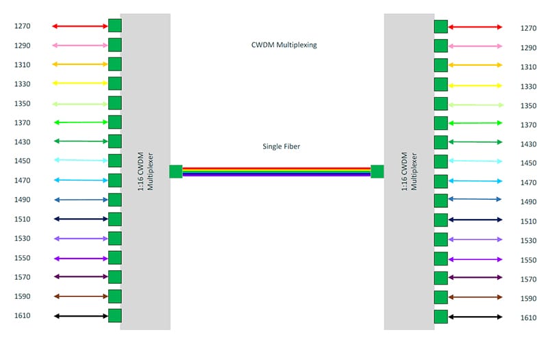
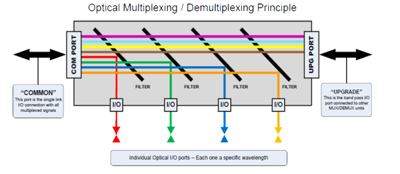
cwdm-channel

Figure 1

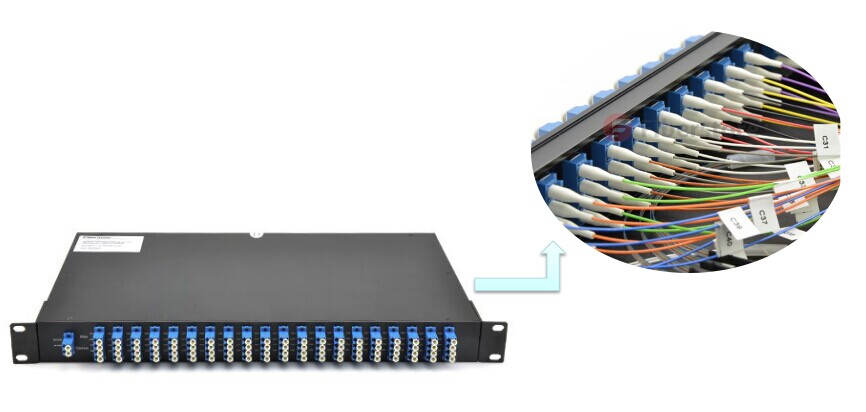
CWDM technology has been applied into wide areas, such as CWDM optical transceivers, CWDM OADM and CWDM Mux/DeMux. CWDM Mux/DeMux modules are multiplexers and demultiplexers which provide long distance coverage with premium optical technology to enhance fibre optic systems. It multiplexes signals of different wavelengths on one single fibre and demultiplexes wavelengths to individual fibres. CWDM Mux/DeMux can offer low-cost bandwidth and upgrade the existing system without leading spare costs on more fibres. CWDM Mux/DeMux can hold up to 18 channels of different standards (for example, Fibre Channel, Gigabit Ethernet) and data rates over one fibre optic link without interruption. FS.COM offers a full series of CWDM Mux/DeMux, including 2, 4, 8, 9, 12, 16, 18 channels with or without monitor port and expansion port in 1RU 19” rack chassis or pigtailed ABS module. The following will show you how to use a 18-channel CWDM Mux/DeMux to increase the data rates up to 180 Gbps on a fibre pair.

In Figure2, all Cisco compatible 10G CWDM SFP+ 1270-1610 nm 40km DOM transceivers on the switch are connected with the CWDM Mux/DeMux by LC-LC fibre patch cords. This CWDM Mux/DeMux has 18 channels and is designed as 1 RU rack mount size, covering the wavelengths from 1270 nm to 1610 nm and supporting LC UPC port. During the long distance transmission, only one single-mode armored LC fibre patch cord is needed to achieve 180 Gbps by connecting the two 18-channel CWDM Mux/DeMux. Thus, it greatly saves the cost for increasing the bandwidth on the existing fibre infrastructure.
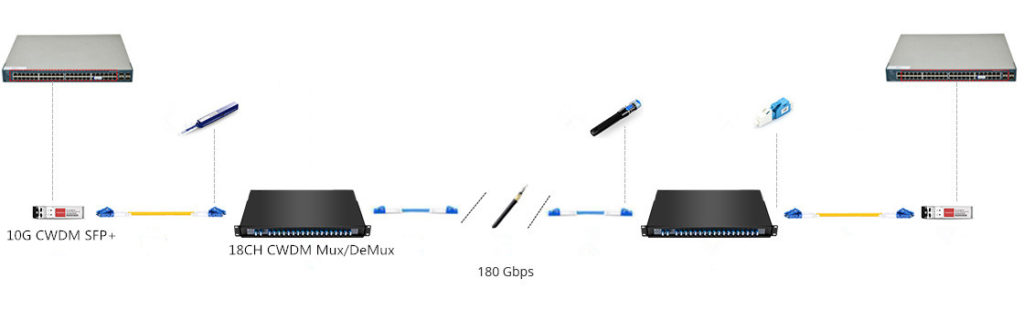
cwdm-mux-18ch

Figure 2

FMU CWDM Mux/Demux

To increase the capacity, it requires more space and cable management is also a big trouble. So FS independently researched and developed FMU CWDM Mux/DeMux to solve this problem. We provide FMU 16-ch 1U Rack CWDM MUX/DEMUX specially designed as 2-slot plug and play style, which allows you to add or remove fibre optic cables and plug-in-modules freely according to your applications. There are two separate CWDM plug-in modules. One is high band (1470nm-1610nm) module with an expansion port and the other is low band (1270nm-1450nm, skip 1390nm, 1410nm) module without expansion port. Via this expansion port, channels can be expanded over one pair of fibre without interruption. You can also insert two CWDM Mux/DeMux FMU-plug-in modules without expansion port for two separated 8-channel connections. Besides, you can mix CWDM and DWDM system by adding CWDM Mux/DeMux FMU-plug-in modules and DWDM Mux/DeMux FMU-plug-in modules with matching wavelengths.
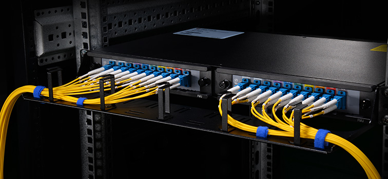
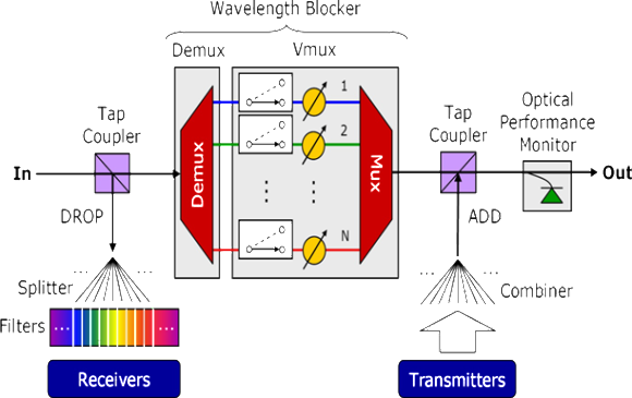
2-slot-cwdm-mux2

Figure 3

FS.COM FMU Plug-in Modules

The table below lists both single fibre and dual fibre FMU plu-in modules for 2-slot CWDM Mux/DeMux. You can choose suitable modules according to you specific requirements. Custom service is available, too.

ID# Description
58215 4 Channels 1270-1610nm Single Fibre CWDM Mux Demux, FMU Plug-in Module, LC/UPC
68215 9 Channels 1270-1610nm Single Fibre CWDM Mux Demux, FMU Plug-in Module, LC/UPC
42972 4 Channels 1270-1330nm Dual Fibre CWDM Mux Demux, FMU Plug-in Module, LC/UPC
43097 8 Channels 1470-1610nm Dual FibreCWDM Mux Demux, FMU Plug-in Module, LC/UPC
43099 8 Channels 1470-1610nm Dual FibreCWDM Mux Demux with Expansion Port, FMU Plug-in Module, LC/UPC
Conclusion

If you would like to increase your network bandwidth while spend less money on changing existing infrastructure, CWDM Mux/DeMux is an economical solution. FS.COM brings you high quality CWDM Mux/DeMux module and newly self-developed FMU 2-slot CWDM Mux/DeMux modules & FMU plug-in modules. For detailed information, please visit our site www.fs.com or contact us through sales@fs.com.

A Wise Decision to Choose DWDM Mux/DeMux

The advent of big data requires for highly efficient and capable data transmission speed. To solve the paradox of increasing bandwidth but spending less, WDM (wavelength division multiplexing) multiplexer/demultiplexer is the perfect choice. This technology can transport extremely large capacity of data traffic in telecom networks. It’s a good way to deal with the bandwidth explosion from the access network.

WDM

WDM stands for wavelength division multiplexing. At the transmitting side, various light waves are multiplexed into one single signal that will be transmitted through an optical fibre. At the receiver end, the light signal is split into different light waves. There are 2 standards of WDM: coarse wavelength division nultiplexing (CWDM) and dense wavelength division multiplexing (DWDM). The main difference is the wavelength steps between the channels. For CWDM this is 20nm (course) and for DWDM this is typically 0.8nm (dense). The following is going to introduce DWDM Mux/Demux.

DWDM Technology

DWDM technology works by combing and transmitting multiple signals simultaneously at different wavelengths over the same fibre. This technology responds to the growing need for efficient and capable data transmission by working with different formats, such as SONET/SDH, while increasing bandwidth. It uses different colors (wavelength) which are combined in a device. The device is called a Mux/Demux, abbreviated from multiplexer/demultiplexer, where the optical signals are multiplexed and de-multiplexed. Usually demultiplexer is often used with multiplexer on the receiving end.

Mux/Demux

Mux selects one of several input signals to send to the output. So multiplexer is also known as a data selector. Mux acts as a multiple-input and single-output switch. It sends optical signals at high speed over a single fibre optic cable. Mux makes it possible for several signals to share one device or resource instead of having one device per input signals. Mux is mainly used to increase the amount of data that can be sent over the network within a certain amount of time and bandwidth.

Demux is exactly in the opposite manner. Demux is a device that has one input and more than one outputs. It’s often used to send one single input signal to one of many devices. The main function of an optical demultiplexer is to receive from a fibre consisting of multiple optical frequencies and separate it into its frequency components, which are coupled in as many individual fibres as there are frequencies.

mux-and-demux

DWDM Mux/Demux modules deliver the benefits of DWDM technology in a fully passive solution. They are designed for long-haul transmission where wavelengths are packed compact together. FS.COM can provide modules for cramming up to 48 wavelengths in 100GHz grid(0.8nm) and 96 wavelengths in 50GHz grid(0.4nm) into a fiber transfer. ITU G.694.1 standard and Telcordia GR1221 are compliant. When applied with Erbium Doped-Fiber Amplifiers (EDFAs), higher speed communications with longer reach (over thousands of kilometres) can be achieved.

Currently the common configuration of DWDM Mux/Demux is from 8 to 96 channels. Maybe in future channels can reach 200 channels or more. DWDM system typically transports channels (wavelengths) in what is known as the conventional band or C band spectrum, with all channels in the 1550nm region. The denser channel spacing requires tighter control of the wavelengths and therefore cooled DWDM optical transceiver modules required, as contrary to CWDM which has broader channel spacing un-cooled optics, such as CWDM SFP, CWDM XFP.

DWDM Mux/Demux offered by FS.COM are available in the form of plastic ABS module cassette, 19” rack mountable box or standard LGX box. Our DWDM Mux/Demux are modular, scalable and are perfectly suited to transport PDH, SDH / SONET, ETHERNET services over DWDM in optical metro edge and access networks. FS.COM highly recommends you our 40-CH DWDM Mux/DeMux. It can be used in fibre transition application as well as data centre interconnection for bandwidth expansion. With the extra 1310nm port, it can easily connect to the existing metro network, achieving high-speed service without replacing any infrastructure.

DWDM MUX DEMUX

Conclusion

With DWDM Mux/DeMux, single fibres have been able to transmit data at speeds up to 400Gb/s. To expand the bandwidth of your optical communication networks with lower loss and greater distance capabilities, DWDM Mux/DeMux module is absolutely a wise choice. For other DWDM equipment, please contact via sales@fs.com.

Optical Multiplexing for High Speed Communication Systems

Introduction

Optical transmission uses pulses of light to transmit information from one place to another through an optical fibre. The light is converted to electromagnetic carrier wave, which is modulated to carry information as the light propagates from one end to another. The development of optical fibre has revolutionized the telecommunications industry. Optical fibre has replaced other transmission media such as copper wire since inception, and is mainly used to wire core networks. Today, optical fibre has been used to develop new high speed communication systems that transmit information as light pulses, examples are multiplexers/demultiplexers using the optical multiplexing technology.

What is Multiplexing?

Multiplexer (Mux) is hardware component that combines multiple analog or digital input signals into a single line of transmission. And at the receiver’s end, the multiplexer is known as DeMultiplexer (DeMux)—performing reverse function of multiplexers. Multiplexing is therefore the process of combining two or more input signals into a single transmission. At receiver’s end, the combined signals are separated into distinct separate signal. Multiplexing enhances efficiency use of bandwidth. Here is a figure which shows the principle of optical multiplexing/demultiplexing.

Principle of Optical Multiplexing and DeMultiplexing

Optical Mux and DeMux are required to multiplex and demultiplex various wavelengths onto a single fibre link. Each specific I/O will be used for a single wavelength. One optical filter system can act as both Mux and DeMux. Optical Mux and DeMux are basically passive optical filter systems, which are arranged to process specific wavelengths in and out of the transport system (usually optical fibre). Process of filtering the wavelengths can be performed using Prisms, Thin Film Filter (TFF), and Dichroic filters or interference filters. The filtering materials are used to selectively reflect a single wavelength of light but pass all others transparently. Each filter is tuned for a specific wavelength.

Components of Optical Multiplexer

Generally, an optical multiplexer consists of Combiner, Tap Couplers (Add/Drop), Filters (Prisms, Thin film, or Dichroic), Splitter, and Optical Fibre. Here is a figure that shows the structure of a common optical multiplexer.

Structure of Optical Multiplexer

Optical Multiplexing Techniques

There are mainly three different techniques in multiplexing light signals onto a single optical fibre link: Optical Time Division Multiplexing (OTDM), Wavelength Division Multiplexing (WDM), and Code Division Multiplexing (CDM).

  1. OTDM: Separating wavelengths in time.
  2. WDM: Each channel is assigned a unique carrier frequency; Channel spacing of about 50GHz; Includes Coarse WDM (CWDM) and Dense WDM (DWDM).
    • CWDM: Characterized by wider channel spacing than DWDM.
    • DWDM: Uses a much narrower channel spacing, therefore, many more wavelengths are supported.
  3. CDM: Also used in microwave transmission; Spectrum of each wavelength is assigned a unique spreading code; Channels overlap both in time and frequency domains but the code guide each wavelength.

Applications

  • The major scarce resource in telecommunication is bandwidth—users want transmit at more high rate and service providers want to offer more services, hence, the need for a faster and more reliable high speed system.
  • Reducing cost of hardware, one multiplexing system can be used to combine and transmit multiple signals from Location A to Location B.
  • Each wavelength, λ, can carry multiple signals.
  • Mux/DeMux serve optical switching of signals in telecommunication and other field of signal processing and transmission.
  • Future next generation internet.

Advantages

  • High data rate and throughput: Data rates possible in optical transmission are usually in Gbps on each wavelength; Combination of different wavelengths means more throughput in one single communication systems.
  • Low attenuation: Optical communication has low attenuation compare to other transport system.
  • Less propagation delay.
  • More services offered.
  • Increase Return On Investment (ROI)
  • Low Bit Error Rate (BER)

Shortcomings

  • Fibre Output Loss and Dispersion: Signal is attenuated by fibre loss and distorted by fibre dispersion, then regenerator are needed to recover the clean purposes.
  • Inability of current Customer Premises Equipment (CPE) to receive at the same transmission rate of optical transmitting systems (achieving all-optical networks).
  • Optical-to-Electrical Conversion Overhead: Optical signals are converted into electrical signal using photo-detectors, switched and converted back to optical. Optical/electrical/optical conversions introduce unnecessary time delays and power loss. End-to-end optical transmission will be better.

Future Work

  • Research in optical end user equipment: Mobile phones, PC, and other handheld devices receiving and transmitting at optical rate.
  • Fast regeneration of attenuated signal.
  • Less distortion resulting from fibre dispersion.
  • End-to-end optical components: Eliminating the need for Optical-to-Electrical converter and vise versa.

Conclusion

While optical transmission is better compare to other transmission media because of its low attenuation and long distance transmission profile, optical multiplexing is useful in signal processing and transmission by transporting multiple signals using one single fibre link. As the growth of the internet requires fibre optic transmission to achieve greater throughput, optical multiplexing is also useful in image processing and scanning application.

Article Source: http://www.fiberopticshare.com/optical-multiplexing-for-high-speed-communication-systems.html