Tag Archives: 10GBASE-LRM

10GBASE-LRM – The New 10G Multimode Optical Solution

10 Gigabit Ethernet has been applied for a long time in data centers and enterprise LANs. For 10G Ethernet connection, there are both single mode and multimode solutions. This post will introduce 10GBASE-LRM – a new 10G multimode optical solution.

First let’s see the original multimode solutions and supportable distances for 10G Ethernet.

10G-multimode solution-supportable-distance

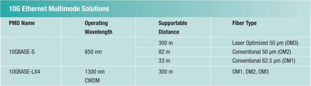
10GBASE-S operates at 850nm wavelength. It can support up to 300m distance over laser-optimised OM3. This makes it a popular standard for data centers and cooperate backbones. For the conventional OM1 and OM2 which are not optimised for laser transmission, the furthest supportable distance is 33 m and 82 m. So these two solutions are only used in equipment rooms or small data centers.

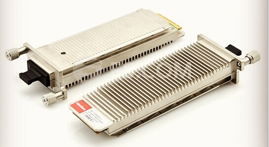
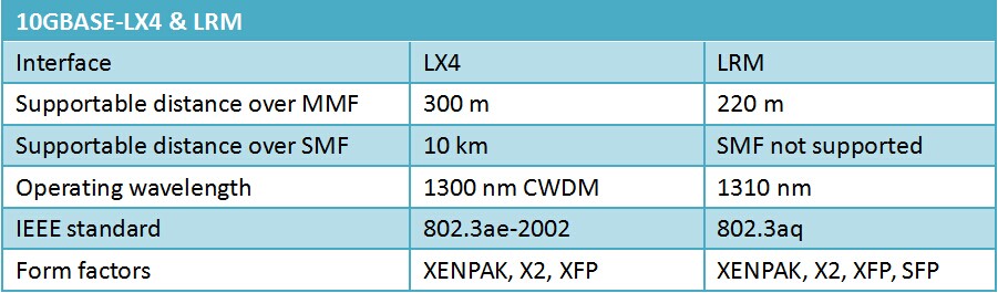
10GBASE-LX4 was specified to support 300 m over three cable types. So it relies on coarse wavelength division multiplexing (CWDM) which is more complex and expensive technology. 10GBASE-LX4 operates at 1300nm wavelength and that requires additional cost on mode-conditioning patch cords (MCPCs).

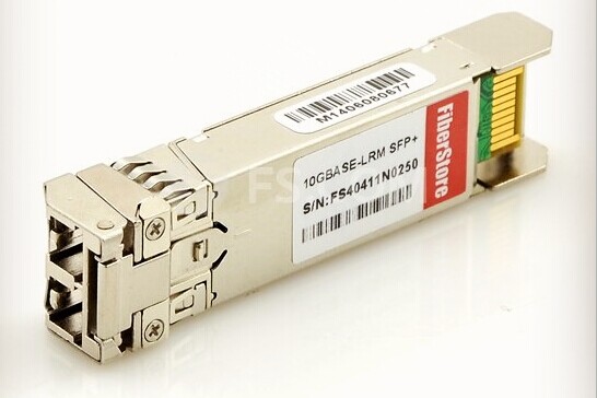
The high cost and relatively slow adoption of 10GBASE-LX4 drive the development of a new standard—10GBASE-LRM. 10GBASE-LRM is developed to offer a longer reach for conventional fibre cables at a lower cost and smaller size than 10GBASE-LX4. The following will talk about 10GBASE-LRM from three sides.

10GBASE-LRM Transmission Distance

On condition the supporting distance, 10GBASE-LRM can only support 220 m. It’s suitable for LAN networks within buildings. But a cabling survey provides that for 10G network, the distance is not able to address 30% of in-building channels.

10GBASE-LRM Electronic Dispersion Compensation

The key to the long reach of 10GBASE-LRM on conventional multimode fibre is electronic dispersion compensation (EDC). EDC is deployed as an integrated circuit that acts like a complex filter on the received signal from the optical fibre. The purpose is to extend the maximum supportable distance. 10GBASE-LRM applies EDC technology and is therefore independent of the optical wavelength. 10GBASE-LRM operates at 1300 nm.

EDC chips is added to a linear detector in the receiver. As an additional component, it increases cost, consumes power and wastes heat. It can only work as intended in conjunction with a linear detector and amplifier. Because the EDC device must operate on a faithful analog rendition of the optical waveform in the fibre. For 10GBASE-LRM, to reproduce the optical waveform with precision, extra requirements and cost on the receiver design are needed.

10GBASE-LRM Multiple Transmit Launch Conditions

In order to improve the chances of operating at a higher bandwidth, 10GBASE-LRM relies on multiple transmit launch conditions.

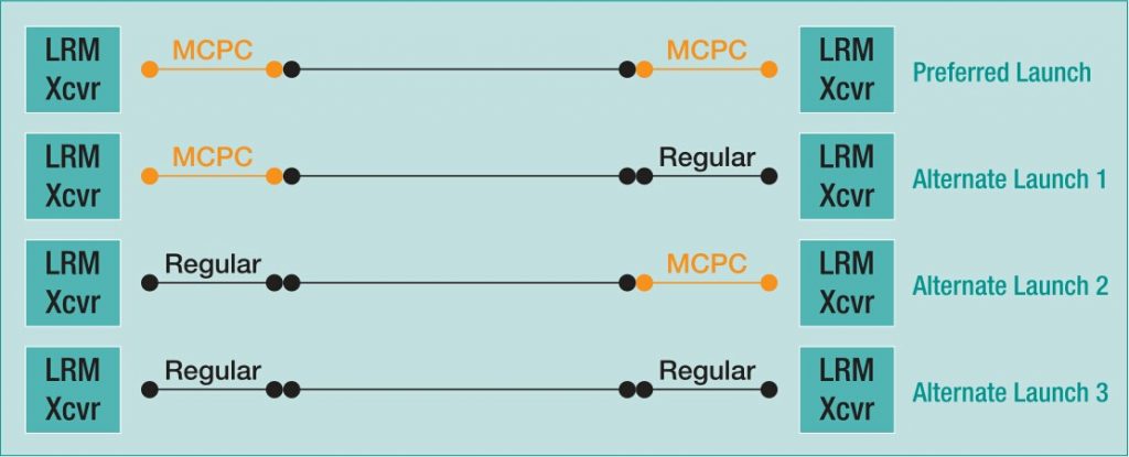
One launch is achieved by using mode-conditioning patch cord. The other launch is produced using a regular multimode patch cord. Through the two launches, different modes can be achieved and a favorable operating condition can be easily found.

There are four possible patch cord combinations at both ends of the channel. The preferred launch uses MCPCs on both ends. This process requires a test for link stability for each configuration. The user should shake and bend the patch cord at the transmit end while observing channel health indicators at the receive end. The shaking and bending of the cords causes changes to the received waveform which the receiver must tolerate in normal operation. If there were transmission errors, then users should change another launch. The errors indicate that the channel is operating near or beyond the limit of the receiver’s capability and the link may fail in operation.

launch-conditions-for-10gbase-lrm

However, the 10GBASE-LRM standard’s committee refuse to implement this channel test. So the burden of the shaking and bending lies on the users. It’s not good for the popularity of 10GBASE-LRM.

Comparison of Several 10G Transceivers Cost

The following will compare the cost of 10G transceivers from several sides, including laser, receiver, package and cords.

Laser: 10GBASE-LRM uses 1310nm fabry perot lasers, which cost fewer than 10GBASE-L’s and 10GBASE-LX4 DFB lasers, but more than 10GBASE-S’s 850nm VCSELs. 10GBASE-LRM requires tighter transmitter waveform control to limit the transmit waveform dispersion penalty that EDC can’t compensate. Thus, it reduces transmitter yields and increases cost.

Receiver: 10GBASE-LRM adds EDC chip cost to receiver and needs a linear detector and amplifier instead of other cheap digital equipment.

Package: 10GBASE-LRM requires a smaller package than 10GBASE-LX4. However, not like 10GBASE-S, 10GBASE-LRM requires higher-cost single-mode transmitter alignment for compatibility with mode conditioning patch cords.

Cords: 10GBASE-LRM needs mode conditioning patch cords for reliable link operation. And the cost is much higher than regular SMF or MMF fibre patch leads.

Through the comparison among these 10G optical transceivers, you may find which one costs fewer. 10GBASE-LRM transceiver is cheaper than 10GBASE-LX4, more expensive than 10GBASE-L and 10GBASE-S transceivers.

Conclusion

10GBASE-LRM is a multimode solution for 10 Gigabit Ethernet. Based on the above content, 10GBASE-LRM has some advantages over 10GBASE-LX4. It offers lower cost and smaller package. But the distance and reliability are not very ideal. Compared with 10GBASE-S, 10GBASE-LRM is not so good as to the cost, simplicity, reliability and distance capability. FS.COM provides various types of cost-effective 10GBASE transceivers, such as 10GBASE-LR, 10GBASE-SR, 10GBASE-ER, etc. Other compatible brands like Cisco, Juniper, Arista, Brocade are also available. Among so many choices, you must choose the most suitable solution for your network connection.

10GBASE-LX4 vs 10GBASE-LRM, Which One Wins?

For 10 Gigabit data transmission, various physical-layer interconnects are available, such as 10GBASE-LX4, CX4, SR, LR and ER as well as 10GBASE-LRM. With so many options, you may be confused which one is the best. This article will discuss two options requiring for multimode fibre cable. They are 10GBASE-LX4 and 10GBASE-LRM. Which one do you think is better?

What’s 10GBASE-LX4

Now maybe 10GBASE-LX4 is not so popular. But it’s not the same case several years ago. This standard is the first optical interface standard developed to run at 10 Gbits/sec over multimode optical fibre backbones in vertical risers. LX4 was robust and stable. Many vendors have produced 10GBASE-LX4 related equipment. Once there was an industry trade group—the LX4-TG (LX4 Trade Group) formed to promote LX4 technology.

10GBASE-LX4

What’s 10GBASE-LRM

Later, the LRM standard is developed by the same IEEE group that generated the 10GBASE-LX4 standard. The specifications can only support the distance of 220 m. At first, technicians intended to stretch the coverage to be 300 m. However, it’s too risky and limited the ability to release the standard in a timely manner. The reduced distance is good for more robust LRM operation, but may limit the product’s applications in some building backbones.

10GBASE-LRM

Performance of 10GBASE-LX4 and 10GBASE-LRM

10g lrm and lx4

10GBASE-LX4 transceiver module can be used for both single-mode or multimode fibre connection with distance up to 10 km and 300 m. LX4 applies CWDM technology using four wavelength—transmitters near 1300 nm, a CWDM multiplexer and demultiplexer, and four receivers. The advantage of this approach is that the transmitters and receivers are all operating at about one-quarter of the data rate; so the data transmission is robust to modal dispersion. But it has the disadvantages of high cost, big size and non-manufacturability.

While 10GBASE-LRM uses wavelength of 1310 nm with a single transmitter and a receiver with an adaptive electronic equalizer IC in the receive chain. LRM module has a simpler optical path. The laser of LRM module can be a distributed-feedback (DFB) laser, a vertical-cavity surface-emitting laser (VCSEL), or a Fabry-Perot (FP) laser. Both DFBs and VCSELs provide a very clean, single-wavelength output, which minimises signal degradation due to spectral effects. And an FP laser source can produce a range of different wavelengths. Different wavelengths travel through the fibre at slightly different speeds, creating additional jitter which will be recovered by the EDC known as adaptive equalization technology. EDC is used to compensate for the differential modal dispersion (DMD) present in legacy fibre channels.

Advantages of 10GBASE-LRM

The 10GBASE-LRM approach has three key advantages over 10GBASE-LX4. The following will give an introduction from three sides.

Size — 10GBASE-LX4 uses four lasers and laser drivers and four photodiodes and preamplifiers, which makes LX4 module a big size. But LRM uses the same optical component footprint as other 10G modules, with EDC functionality.

Cost — 10GBASE-LRM devices cost less than 10GBASE-LX4 equipment. From the point of manufacturing yields and packaging and assembly cost, the price of LX4 is higher than that of other short reach 10G modules. By contrast, LRM substitutes low-cost silicon for the optical complexity of LX4. So it greatly reduces the cost.

Assembly — 10GBASE-LX4 requires a significant amount of assembly (splicing, fibre attach and routing, and in some cases multiple personal computer boards, flex cables, etc.). Thus it naturally reduces yields at the module level and makes the module difficult to be manufactured. However, LRM requires no extra assembly compared with existing 10G SR SFP+ or 10G LR SFP+ modules.

Conclusion

10GBASE-LX4, as the first standard developed for 10GBASE data rate over multimode fibre backbones, has its special significance in the fibre optic communication history. As technology is continuously developing, so better objects will be created and replace the not so good ones. LRM is another standard for 10GBASE. It turns to be more popular with its smaller size, lower cost and greater manufacturability. So 10GBASE-LRM SFP is a good choice for your 10GBASE network. FS.COM offers Brocade 10G-SFP-LRM compatible 10GBASE-LRM SFP 1310nm 220m DOM transceivers and other 10G SFP modules. Each transceiver has been tested on full range of Brocade equipment to keep 100% compatibility. Any service, please contact via sales@fs.com.

Understanding Fiber Optic Based Light Source

Each piece of active electronics will have a variety of light sources used to transmit over the various types of fiber. The distance and bandwidth will vary with light source and quality of fiber. In most networks, fiber is used for uplink/backbone operations and connecting various buildings together on a campus. The speed and distance are a function of the core, modal bandwidth, grade of fiber and the light source, all discussed previously. Light sources of the fiber light source are offered in a variety of types. Basically there are two types of semiconductor light sources available for fiber optic communication – The LED sources and the laser sources.

Using single mode fiber for short distances can cause the receiver to be overwhelmed and an inline attenuator may be needed to introduce attenuation into the channel. With Gigabit to the desktop becoming commonplace, 10Gb/s backbones have also become more common. The SR interfaces are also becoming common in data center applications and even some desktop applications. As you can see, the higher quality fiber (or laser optimized fiber) provides for greater flexibility for a fiber plant installation. Although some variations ( 10GBase-LRM SFP+ and 10GBASE-LX4) support older grades of fiber to distances 220m or greater, the equipment is more costly. In many cases, it is less expensive to upgrade fiber than to purchase the more costly components that also carry increased maintenance costs over time.

Light sources of the fiber light source are offered in a variety of types. Basically there are two types of semiconductor light sources available for fiber optic communication – The LED sources and the laser sources.

In fiber-optics-based solution design, a bright light source such as a laser sends light through an optical fiber, called laser light source . Along the length of the fiber is an ultraviolet-light-treated region called a “fiber grating.” The grating deflects the light so that it exits perpendicularly to the length of the fiber as a long, expanding rectangle of light. This optical rectangle is then collimated by a cylindrical lens, such that the rectangle illuminates objects of interest at various distances from the source. The bright rectangle allows line scan cameras to sort products at higher speeds with improved accuracy.

The laser fiber-based light source combines all the ideal features necessary for accurate and efficient scanning: uniform, intense illumination over a rectangular region; a directional beam that avoids wasting unused light by only illuminating the rectangle; and a “cool” source that does not heat up the objects to be imaged. Currently employed light sources such as tungsten halogen lamps or arrays of light-emitting diodes lack at least one of these features.