
This year, Cisco unveiled the Catalyst 9000 family, shaping the new era of intent-based networking. The Network. Intuitive. The Cisco Catalyst 9000 Series switches are the next generation of enterprise-class switches built for security, Internet of Things (IoT), mobility, and cloud. The Cisco Catalyst 9000 Series switches come in three main varieties: The Catalyst 9300, the Catalyst 9400 and the Catalyst 9500. Here, the post will give an emphasis on Cisco Catalyst 9400 series switches and transceiver solution for them.
The Catalyst 9300 Series is the next generation of the industry’s most widely deployed stackable switching platform. Built for security, IoT, and the cloud, these network switches form the foundation for Cisco’s Software-Defined Access, the leading enterprise architecture. In addition, the Cisco Catalyst 9300-based models support a variety of uplink modules for both copper and fibre uplink support. These models add even more flexibility to the interface choices that you can make in a single Cisco Catalyst 9300 Switch or in a stack of Cisco Catalyst 9300 Switches.
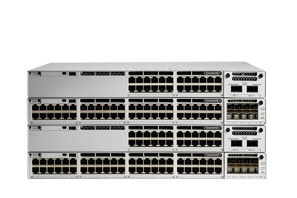
The Cisco Catalyst 9300 Series Switches support optional network modules for uplink ports. All modules are supported across all 9300 platforms:
- 4 x 1 Gigabit Ethernet network module
- 4 x 1, 2.5, 5, or 10 Gigabit Ethernet network module
- 8 x 10 Gigabit Ethernet network module
- 2 x 40 Gigabit Ethernet network module
100G Solution
| Model Number | Transceiver Description | Interface | Max Cable Distance |
| CFP-100G-SR10 | 100GBASE-SR10 CFP form factor transceiver module for multi mode fibre, short wavelength over 10 lanes, in the 850-nm wavelength window | MTP/MPO-24 | Up to 100m on OM3/<150m on OM4 |
| CFP-100G-LR4 | 100GBASE-LR4 CFP form factor transceiver module for SMF, 4 LAN-WDM lanes in the 1310-nm wavelength window | LC duplex | 10km |
| CFP-100G-ER4 | 100GBASE-ER4 CFP form factor transceiver module for SMF, 4 LAN-WDM lanes in the 1310-nm wavelength window | LC duplex | 40km |
| QSFP-100G-SR4-S | 100GBASE-SR4 QSFP form factor transceiver module for multi mode fibre, short wavelength over 4 lanes, in the 850-nm wavelength window | LC duplex | 100m |
| QSFP-100G-CWDM4-S | 100GBASE CWDM4 QSFP form factor Transceiver for single mode fibre, 4 CWDM-WDM lanes in the 12761-1331-nm wavelength window | LC duplex | 2km |
| QSFP-100G-PSM4-S | 100GBASE PSM4 QSFP form factor transceiver module for single mode fibre, short wavelength over 4 lanes, in the 1195-1325-nm wavelength window | MTP/MPO-12 | 500m |
| QSFP-100G-LR4-S | 100GBASE-LR4 QSFP form factor transceiver module for SMF, 4 LAN-WDM lanes in the 1310-nm wavelength window | LC duplex | 10km |
40G Solution
| Model Number | Transceiver Description | Interface | Max Cable Distance |
| QSFP-40G-SR4 | 40GBASE-SR4 QSFP+ transceiver module for MMF, 4-lanes, 850-nm wavelength | MTP/MPO | 150m on OM4 |
| QSFP-40G-CSR4 | 40GBASE-CSR4 QSFP+ transceiver module for MMF, 4-lanes, 850-nm wavelength | MTP/MPO | 400m on OM4 |
| QSFP-40G-SR4-S | 40GBASE-SR4 QSFP+ transceiver module for MMF, 4-lanes, 850-nm wavelength | MTP/MPO | 150m on OM4 |
| QSFP-40G-SR-BD | 40G QSFP Bi-Directional transceiver module for duplex MMF | LC duplex | 150m on OM4/100m on OM3/30m on OM2 |
| QSFP-40G-ER4 | 40GBASE-LR4 QSFP40G transceiver module for Single Mode Fibre, 4 CWDM lanes in 1310nm window Muxed inside module | LC duplex | 40km |
| QSFP-40GE-LR4 | 100GBASE-LR4 QSFP form factor transceiver module for SMF, 4 LAN-WDM lanes in the 1310-nm wavelength window | LC duplex | 10km |
| WSP-Q40GLR4L | 40GBASE-LR4 QSFP40G transceiver module for Single Mode Fibre, 4 CWDM lanes in 1310nm window Muxed inside module | LC duplex | 2km |
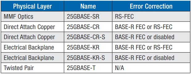
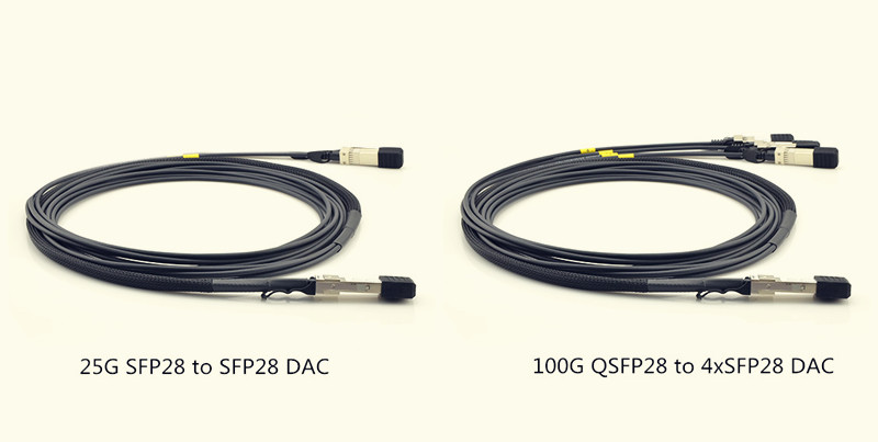
25G Solution
| Model Number | Transceiver Description | Connector Type | Cable Type |
| SFP-H25G-CU1M | 25G Copper Cable 1-meter | SFP28 to SFP28 | Passive Copper Cable |
| SFP-H25G-CU2M | 25G Copper Cable 2-meter | SFP28 to SFP28 | Passive Copper Cable |
| SFP-H25G-CU3M | 25G Copper Cable 3-meter | SFP28 to SFP28 | Passive Copper Cable |
| SFP-H25G-CU5M | 25G Copper Cable 2-mete | SFP28 to SFP28 | Passive Copper Cable |
| SFP-25G-SR-S | 25GBASE-SR SFP+ transceiver module for MMF, 850-nm wavelength | LC duplex | MMF |
10G Solution
| Model Number | Transceiver Description | Interface | Max Cable Distance |
| SFP-10G-SR | 10GBASE-SR SFP+ transceiver module for MMF, 850-nm wavelength | LC duplex | 300m over OM3 |
| SFP-10G-SR-S | 10GBASE-SR SFP+ transceiver module for MMF, 850-nm wavelength | LC duplex | 300m over OM3 |
| SFP-10G-SR-X | 10GBASE-LRM SFP+ transceiver module for MMF and SMF, 1310-nm wavelength | LC duplex | 300m over OM3 |
| SFP-10G-LRM | 10GBASE-LRM SFP+ transceiver module for MMF and SMF, 1310-nm wavelength | LC duplex | 220m |
| SFP-10G-LR | 10GBASE-LR SFP+ transceiver module for SMF, 1310-nm wavelength | LC duplex | 10km |
| SFP-10G-LR-S | 10GBASE-LR SFP+ transceiver module for SMF, 1310-nm wavelength | LC duplex | 10km |
| SFP-10G-LR-X | 10GBASE-LR SFP+ transceiver module for SMF, 1310-nm wavelength | LC duplex | 10km |
| SFP-10G-ER-S | 10GBASE-ER SFP+ transceiver module for SMF, 1550-nm | LC duplex | 40km |
| SFP-10G-ZR | 10GBASE-ZR SFP+ transceiver module for SMF, 1550-nm | LC duplex | 80km |
| SFP-10G-BX40D-I | 10G SFP+ Bidirectional for 40km, downstream | LC duplex | 40km |
| SFP-10G-BX40U-I | 10G SFP+ Bidirectional for 40km, upstream | LC duplex | 40km |
| DWDM-SFP10G-49.32 | 10GBASE-DWDM 1549.32 nm SFP+ (100-GHz ITU grid) | LC duplex | 40km |
| DWDM-SFP10G-60.61 | 10GBASE-DWDM 1560.61 nm SFP+ (100-GHz ITU grid) | LC duplex | 40km |
| CWDM-SFP10G-1470 | CWDM 1470 nm SFP+ 10 Gigabit Ethernet Transceiver Module | LC duplex | 20km |
| CWDM-SFP10G-1490 | CWDM 1490 nm SFP+ 10 Gigabit Ethernet Transceiver Module | LC duplex | 20km |
| XENPAK-10GB-ER | 10GBASE-ER XENPAK transceiver module for SMF, 1550-nm wavelength | SC duplex | 40km |
| XENPAK-10GB-LR | 10GBASE-LR XENPAK transceiver module for SMF, 1310-nm wavelength | SC duplex | 10km |
| X2-10GB-LR | 10GBASE-LR X2 transceiver module for SMF, 1310-nm wavelength | SC duplex | 10km |
| X2-10GB-SR | 10GBASE-SR X2 transceiver module for MMF, 850-nm wavelength | SC duplex | 300m over OM3 MMF |
| XFP-10GLR-OC192SR | Cisco multirate XFP transceiver module for 10GBASE-LR Ethernet and OC-192/STM-64 short-reach (SR-1) Packet-over-SONET/SDH (POS) applications,SMF | LC duplex | 10km |
| XFP-10GER-OC192IR | Cisco multirate XFP transceiver module for 10GBASE-ER Ethernet and OC-192/STM-64 intermediate-reach (IR-2) Packet-over-SONET/SDH (POS) applications, SMF | LC duplex | 40km |
Conclusion
Digital disruption is changing how we think about our networks. Whether customers or employees, the “experience” has become a strategic imperative. The Cisco Catalyst 9300 Series fixed access switches are designed to help you change your network from a platform of connectivity to a platform of services. If you are in need of compatible optical transceivers for Catalyst 9300, give FS.COM a shot. FS.COM provides a wide range of supported optical transceivers for Cisco Catalyst 9300 series switch. Each one of them has been tested with assured 100% compatibility to them.
Related Article: Cisco Catalyst 3750 Series Switches SFP Port Connections
 As fibre deployment has become mainstream, splicing has naturally crossed from the outside plant (OSP) world into the enterprise and even the data centre environment. Fusion splicing involves the use of localized heat to melt together or fuse the ends of two optical fibres. The preparation process involves removing the protective coating from each fibre, precise cleaving, and inspection of the fibre end-faces. Fusion splicing has been around for several decades, and it’s a trusted method for permanently fusing together the ends of two optical fibres to realize a specific length or to repair a broken fibre link. However, due to the high costs of fusion splicers, it has not been actively used by many people. But these years some improvements in optical technology have been changing this status. Besides, the continued demand for increased bandwidth also spread the application of fusion splicing.
