
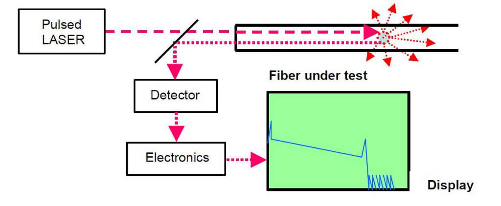
As the use of fibre in premise networks continues to grow, so do the requirements for testing and certifying it. An optical time-domain reflectometer (OTDR) is an electronic-optical instrument used to characterize optical fibres. It locates defects and faults, and determines the amount of signal loss at any point in an optical fibre by using the effects of Rayleigh scattering and Fresnel reflection. By sending a pulse of light into a fibre and measuring the travel time (“time domain”) and strength of its reflections (“reflectometer”) from points inside the fibre, it produces a characteristic trace, or profile, of the length vs. returned signal level on a display screen (as shown in the following picture). This article will describe the key specifications that should be considered when choosing an OTDR.
When choosing an OTDR, it is important to select the specific OTDR performance and features according to the required specifications listed below.
The dynamic range of an OTDR determines how long of a fibre can be measured. The total optical loss that an OTDR can analyze is mainly determined by the dynamic range. The dynamic range affects the accuracy of the link loss, attenuation and far-end connector losses. Thus, having sufficient dynamic range is really important. The manufacturers specify dynamic range in different way. The higher the dynamic range, the longer the distance an OTDR can analyze.
Dead zone refers to the space on a fibre trace following a Fresnel reflection in which the high return level of the reflection covers up the lower level of backscatter. To specify an OTDR’s performance, it is important to analyze the dead zone and ensure the whole link is measured. Dead zones are characterized as an event dead zone and an attenuation dead zone. Event dead zone refers to the minimum distance required for consecutive reflective events to be “resolved” (for example, to be differentiated from each other). Attenuation dead zone refers to the minimum distance required, after a reflective event, for the OTDR to measure a reflective or non-reflective event loss.
There are two resolution specifications: loss (level), and spatial (distance). Loss resolution is the ability of the sensor to distinguish between levels of power it receives. When the laser pulse gets farther out in the fibre, the corresponding backscatter signal gets weaker and the difference between backscatter levels from two adjacent measurement points becomes larger. Spatial resolution is how close the individual data points that make up a trace are spaced in time (and corresponding distance). The OTDR controller samples the sensor at regular time intervals to get the data points. If it takes readings from the sensor very frequently, then the data points will be spaced close together and the OTDR can detect events in the fibre that are closely spaced.
This is an important feature because a great deal of time can be saved in the analysis of OTDR traces if the user is able to set pass/fail thresholds for parameters of interest (such as splice loss or connector reflection). These thresholds highlight parameters that have exceeded a warning or fail limit set by the user and, when used in conjunction with reporting software, it can rapidly provide re-work sheets for installation/commissioning engineers.
Report generation could be another major time saver. For example, some OTDRs with specialized post-processing software allow fast and easy report generation, which might reduce the post-processing time up to 90 percent. These reports also include bidirectional analyses of OTDR traces and summary reports for high-fibre-count cables.
Some OTDRs are designed to test long distance optical fibres and some others to test short distance optical fibres. For example, if you are to test premises fiber networks where short distance optical fibres are installed, OTDRs designed for testing long distance optical fibres are not suitable. Besides, knowing your users and the time it will cost is also necessary. Because some types of OTDRs are easy to use and some others are complicated to set up.
When selecting an OTDR, you’re supposed to take all the above factors into consideration. Fiberstore supplies a wide range of OTDRs available with various fibre types and wavelengths (including single-mode fibre, multi-mode fibre, 1310nm, 1550 nm, 1625 nm, etc). They also supply OTDRs of famous brands, such as JDSU MTS series, EXFO FTB series, YOKOGAWA AQ series and so on. OEM portable and handheld OTDRs are available as well.