Category Archives: Network Media Conversion

All-optical Switch Overview

Nowadays the growing demand for optical capacity has fueled the development of long-haul optical network systems. As one of perfect solutions for higher bandwidth, WDM technology is widely applied for its multiple transmission channels. However, WDM only delivers raw capacity and the bandwidth needed to be managed by carriers: optical switches. This article will depict one kind of optical switch: all-optical switch in the following content.

Introduction of All-optical Switch

All-optical switch is a device that enables phonotic signals in optical fibers or integrated optical circuits (IOCs) to be switched directly form one circuit to another. It manipulates signals in the form of light, either by redirecting all signals in a fiber or by selecting signals at certain wavelengths in wavelength-division multiplexed systems. It is a lower-cost solution for there is no need for expensive high-speed electronics in the switching process.

Technology of All-optical Switch

There are numerous technologies as how to implement light switching between optical fibers. One of commonly used technologies for developing an economically viable, scalable all-optical switch is micro-electromechanical system (MEMS). MEMS consists of mirrors no larger in diameter that are arranged on special pivots so that they can be moved in three dimensions (3D). Light from an input fiber is aimed at mirror, which is directed to move the light to another mirror on a facing array. Then the mirror reflects the light down towards the desired output fiber. As so many mirrors on a single chip, the cost per switching element is relatively low.

Advantages of All-optical Switch

All-optical switch is a lower-cost solution for there is no need for expensive high-speed electronics in the switching process by using MEMS technology. It can provide a 96% reduction in power consumption. It performs the same function as the OEO switches but features higher performance. All-optical switches can support 1000×1000 ports which are available in a space of two to four bays of equipment. A 3D all-optical switches is even expected to support 8000×8000 ports in the future. Thus all-optical switch makes the networks more flexible and even more dynamic.

Fiberstore SolutionsFiberstore offers a wide range of MEMS switches with different configurations include 1×4, 1×8 and 1×16 configurations for single-mode or multimode fibers. Details information are as follows. All these solutions are highly against environmental variations of temperature and vibration with unmatched low cost due to its novel and unique design. They are tested in-house prior to shipment with commitment that they will reach the destination in perfect physical and working condition. For more information, please visit www.fs.com.

Advanced Optical Components – Optical Switch

Optical switch (or fibre optic switch) can be a mechanical, opto-mechanical, or electronic device that opens or closes an optical circuit. The optical switch can be used to complete or break an optical path. Passive fibre optic switches will route an optical signal without electro-optical or opto-electrical conversion. However, a passive optical switch may use an electromechanical device to physically position the switch. An optical switch may have one or more input ports and two or more output ports. Here is an opto-mechanical optical switch with one input port and four output ports, that is, a 1 × 4 Optical Switch).

Fiberstore's 1 × 4 Opto-Mechanical Optical Switch

As with any other type of switch, the optical switch has many uses, depending on the complexity of the design. In essence, the switch is the control for making, breaking, or changing the connections within an optical circuit. This definition can be expanded to incorporate the concept of the switch as the control that interconnects or transfers connections from one optical circuit to another.

According to the operating principle and function, there are three types of optical switches: Opto-Mechanical Switch, Thermo-Optic Switch, Electro-Optic Switch. Note: FS has been expanding the product line of optical switches, but not include the thermo-optic and electro-optic switches yet.

Opto-Mechanical Switch

An opto-mechanical switch redirects an optical signal by moving fibre or bulk optic elements by means of mechanical devices. These types of optical switches are typically stepper motor driven. The stepper will move a mirror that directs the light from the input to the desired output, as shown in the figure below. Although opto-mechanical switches are inherently slow due to the actual physical movement of the optical elements, their reliability, low insertion losses, and minimal crosstalk make them a widely deployed type of optical switch.

Structure of Opto-Mechanical Optical Switch

The opto-mechanical switch works on the premise that the input and output light beams are collimated within the fibre and “matched” within the switching device (the beams are moved within the device to ensure the switched connection from the inputs to the outputs). The opto-mechanical switch can be physically larger than alternative switches, but there are many micromechanical fibre optic switches becoming available, such as the Micro Electro Mechanical Systems (MEMS) optical switch. Here is a Mini 1 × 4 Opto-Mechanical Switch and an 1 × 8 MEMS Optical Switch from FS.

Mini 1 × 4 Opto-Mechanical Switch 1 × 8 MEMS Optical Switch

Thermo-Optic Switch

The thermo-optic switch is based on waveguide theory and utilises waveguides made in polymers or silica. In other words, this optical switch utilises the thermal/refractive index properties of the device’s material. The principle of this switch relies on the altering of the waveguide’s refractive index due to a temperature change.

The temperature change can be accomplished in many ways, but generally the device is heated by using a resistive heater, which has the effect of slowing down light in one of the paths. The device then combines the light in the two paths in a constructive or destructive effect, making it possible to attenuate or switch the signal. This type of switch is inherently slow due to the time it takes to heat the waveguide. It’s like a burner on an electric stove: it takes a while to heat up and a while to cool down.

This type of device typically has less optical loss than the opto-mechanical switch. Thermo-optic switches are attractive for several reasons: they work well in low optical power applications, are small in size, and have the potential to be integrated with a number of devices based on silicon wafer theory.

Electro-Optic Switch

Electro-optic refers to a variety of phenomena that occur when an electromagnetic wave in the optical spectrum travels through a material under the stress of an electric field. An electro-optic switch is based on the changing of the refractive index of a waveguide by using an electric field. This device is semiconductor-based and therefore boasts high speed and low optical power loss similar to that of the thermo-optic devices. This device is still in the research stage; however, the technology is rapidly advancing.

Optical switches can be used in a variety of applications, large and small. The use of a fibre optic switch allows data to be routed where and when it is needed. It is important to be aware of the basic parametre for an optical switch when choosing a right one. Some of the performance parametres to consider are Required Size (the number of input and output ports), Optical Fibre Type, Connector Type, Centre Wavelength, Bandwidth, Losses, Crosstalk, Switching Speed, Durability (number of switching cycles), Power Handling, and Repeatability (the amount of change in output power each time the switch changes state). Note: Most of the parametres above are mentioned in the previous post: The Basic Parametres of Passive Optical Network Devices.

The VGA interface to HDMI converter solution

Convert any VGA or Component video with audio into perfect HDMI video signal with integrated audio. Which means you can connect any computer that outputs VGA or another video player that outputs component video (red, green, and blue RCA connection). This converter contains a scaling capability which will fit numerous VGA and Component Video resolutions for your HDMI TV. This ensures easy set-up. You will never need to bother about fiddling around on your computer’s resolutions just to match your HDMI TV, just to change it out again when you need to use your computer monitor.

This is simply not something we take lightly right here at FS. VGA to HDMI conversion has been one of the priority list toppers for us because we all know there are a number of people who require a reliable and simple solution that’s very simple on the wallet. After about a year of looking around and testing unit after unit, we’ve finally found one that is inexpensive and has got the job finished right if you are needing 720p.

BEST VALUE: VGA TO HDMI CONVERTER WITH SCALING (As Much As 720P)

We’ve tested this VGA to HDMI Converter and it works very well. We take VGA to HDMI quite seriously, having tested many units throughout the last couple of years. This device has got the cost effective on the market, converting up to 720p perfectly without any bands of color, artifacts, or blips that other modestly priced VGA to HDMI scalers can occasionally have. Obviously, if you’re wanting 1080p with scaling, you’ll need to invest more than 3 times the money. Or you can take a look at the VGA to HDMI without scaling.

TESTED IN HOUSE

Our engineers found this device to work perfectly, with no bands of color striping the picture, no artifacts or blips, just perfect 720p digital video reproduction of the analog source (VGA and component). A 2-second adjustment of the HDTV’s vertical and horizontal on-screen fixed any slight black border around the picture.

SHOULD I GET THIS 720P SCALER OR A 1080P SCALER?

The solution lies within what size your HDTV is. If you’re able to honestly identify the difference between 1080p and 720p on your HDTV, then get the VGA to HDMI with 1080p scaler. In general we’d recommend 720p scalers for HDTVs less than 37 inches. If you’re planning on reading text from your VGA computer on your HDMI TV, then 720p could also be preferred as it can make the characters big enough to read from across the room.
Other Similar Product Solutions

FS Suggestion for VGA to HDMI Format Conversion and Scaling up to 1080p

As described in greater detail below, Scaling is when you are converting a video format and you will need to go to a new resolution. As an example, if your VGA resolution is 1024 x 768 and you’re converting to 1080p, you may need a scaler. We advise the VGA to HDMI with scaler which handles the job cleanly and perfectly with easily adjustable resolutions (that will actually fit your HDTV unlike another models we’ve tested).

Scaling is when you are converting a video format and also you need to go to a different resolution. As an example, if your VGA resolution is 1024 x 768 and you’re converting to 1080p, you will need the VGA to HDMI with scaler.

720P OR 1080P?

If you are attempting to decide regardless of whether you actually want to invest the extra money for the 1080p capabilities, maybe this helps. How big is your HDTV? If it’s 37 inches or smaller, chances are your TV either doesn’t even support 1080p or it does not matter as it looks virtually exactly the same, especially as you approach 32 inches or smaller. If you have not a 42 inch TV or larger, and you intend on by using this scaler to read text from your VGA source, 720p will in fact figure out well since the text is going to be larger. You’ll find yourself using 720p for reading normal sized text from across the room. If it’s mainly video that you’ll be watching and you’ve got a TV bigger than 37 inches, and you consider yourself a “videophile” or one the obsessively loves high definition, then the extra cash for a 1080p VGA to HDMI scaler is usually recommended.

WHY THE CONVERSION BOX?

You may be wondering the reason why you will have to purchase a conversion box that is obviously more costly than your average little inexpensive passive adapter. The main reason lies inside the type of signal that is being transmitted. VGA (or Video Graphics Array) is purely an analog signal. There has been several successors to VGA (like SVGA, XGA, all the way to QXGA) but this only means the resolution at which the signal can be seen (QXGA supports a solution up to 2048×1536). HDMI however is a digital signal, using a DVI type of video signal (Digital Video Interface). So the major reason for the converter box is to translate an Analog signal to a digital one.

We recommend you stick with one of the two VGA to HDMI converters talked about above. The below solutions still work well for specific scenarios and are worth mentioning.

FS Suggestion for Straight Format Conversion (without scaling):

We recommend you choose VGA to HDMI Format Converter With Audio for converting VGA to HDMI. This box handles the work cleanly without artifacts or another unfixable problems. This box doesn’t scale, however. Which means that there are limited resolutions available. We tested it to display 1024×768, but better resolutions are most likely possible according to your VGA source. This method also permits the addition of analog stereo audio (RCA) that enable you to embed audio into your HDMI signal and also permits you to choose whether you’re converting an RGB (VGA style) or Component signal.

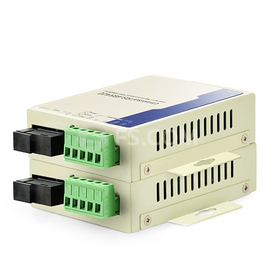
Fibre Media Converters: Unmanaged Media Converter, Fiber Media Converter – FS
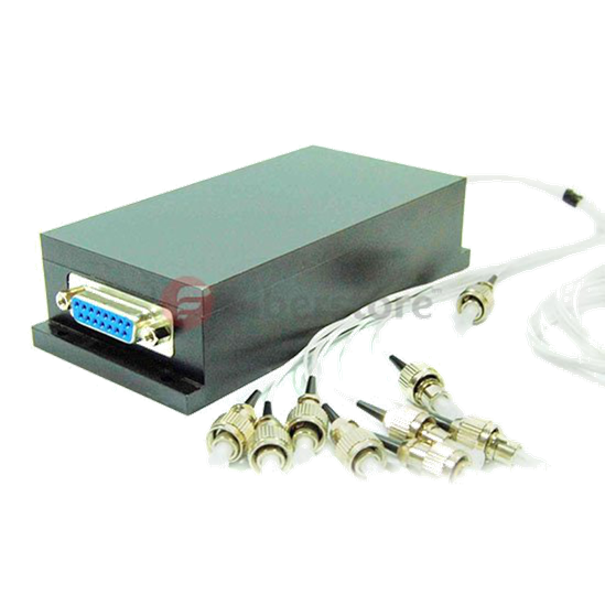
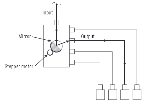
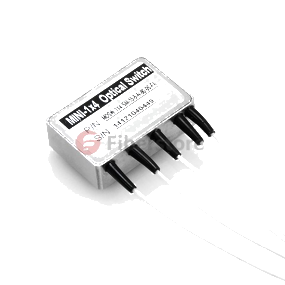
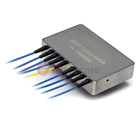
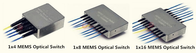
PoE media converter From FiberStore

PoE/PoE+ PSE Media Converter 

The PoE/PoE+ PSE Media Converter not only enables you to connect copper cables to long-distance fiber data links, it also safely powers compatible devices plugged in on the copper side.

Fully compliant with the 802.3af Power over Ethernet (PoE) standard, the converter functions as power source equipment (PSE) to provide -48 VDC power via copper wiring to access points, cameras, and similar devices in areas without nearby power outlets.

For equipment protection, it offers overcurrent and undercurrent detection, as well as fault protection input and power monitoring. It also has powered device signature sensing to detect when a 802.3af compliant device is connected downstream.

The distinct of PoE & PoE+

PoE
Consumes less than 10 Watts (heating) plus PSE power IEEE802.3af Power to field <15.5 Watts.
Input Specifications: 100-240 ±10% VAC, 50/60Hz, 0.5A to 0.2A.
Operating Temperature:+32° to +122° F (0° to +50° C)

PoE+ Giga-basic: Consumes less than 10 Watts (heating) plus PSE power IEEE802.3af/at Power to field <50 Watts (2×24.5 W).
Input Specifications: 100-240 ±10% VAC, 50/60Hz, 1.6A to 0.7A.
Operating Temperature:+32° to +104° F (0° to +40° C)

PoE PD Media Converter

Powered by PoE switches, mid-span hubs, or other 802.3af power source equipment (PSE). Works as a powered device (PD) that receives its power from the spare pairs of copper data cable

Because the converter is compatible with 802.3af PoE standard, it draws its power via UTP cable connected to a PoE PSE, such as a PoE switch. This setup makes the converter ideal for remote areas of a network without AC power outlets.

Power over Ethernet (PoE) is a technology that allows both data and power to be transmitted over standard Cat5 copper cable. Power over Ethernet (PoE) is a flexible, cost-effective solution because it carries both data and power over the same Ethernet cable. That enables operators to install and power PoE-enabled remote devices anywhere and Ethernet connection is available. It’s perfect for wireless access points, video surveillance, security cameras, building management, retail video kiosks, and more, making it possible to easily install or move a device with minimum disruption and cost.

Some Information About Optical Multiplexer Technology

In the long-distance optical fiber transmission,the fiber cables have a small effect on the optical signal transmission,the transmission quality of optical fiber transmission system mainly depends on the optical multiplexers’ quality,because optical multiplexer is responsible for electrical/optical and optical/electric conversion and optical transmitting and receiving. Optical fiber multiplexer as terminal equipment of transmission optical signal, usually used in pairs, divided into optical receiver and optical transmitter, optical transmitter is used to convert electrical signals into optical signals to realize electrical/optical conversion, and the optical signal input optical fiber transmission.Optical receiver is used to restore a in the optical fiber for optical signal into electrical signal to realize optical/electric conversion. It’s fit and unfit quality directly affects the whole system, so you need to know something about the performance and application of the fiber optic multiplexers, it can help you better configuration and procurement.

What is Video Multiplexer?

Fiber optic video multiplexer is used to transform video signals to fiber optic signals, it is analog fiber optic video multiplexer and digital video multiplexer, the digital one is more and more used and it is the popular model in current market. This product is generally used in security applications to control and monitor the video camera signals.

Fiber Optic Multiplexer Technology:

Fiber optic multiplexer technology serves single-mode and multimode optical fibers with multichannel rack mount or standalone units. Multiplexers aren’t only for connecting multiple devices across a network. Multiplexers are also commonly used to distribute data from a SONET core, allowing for the distribution of DS-1, DS-3, and other circuit mode communications to several devices throughout a network. Again, this allows for multiple devices to share an expensive resource.

Used by cellular carriers, Internet service providers, public utilities, and businesses, fiber optic multiplexer technology extends the reach and power of telecommunications technologies. Network management systems allow for system service and maintenance, and provide for security, fault management, and system configuration. With advantages like lower costs and longer life expectancies, current fiber-optical networks are aided by improvements in multiplexing technology, and may provide light speed data transmission well into the future. Multiplexed systems also simplify system upgrades since numbers of channels and channel bandwidth is a function of the electronics rather than the transmission line or components.

FeatureS Of Optical Multipexer:

Fiberstore fiber optic video multiplexer adopt the international advanced digital video and optical fiber transmission technology, these fiber optic multiplexers are various models and can be custom made according to customers’ requirement. Our products can transmit from 1 channel video signal to max 64 channel video signals in different optional distances. They can be with optional audio channel and reverse data channel. Interfaces can be RS232, RS422 or RS485. Fiber optic ports are typical FC, with SC or ST optional. The fiber optic video multiplexers are single mode types and multimode types, used with different kinds of optical fiber lines.We provide some types of optical multiplexers, including video multiplexers,video & data multiplexers,video & audio multiplexers, video & data & audio multiplexers, and we supply optical multiplexer in different channels,such as 1, 2, 4, 8, 16, 24, 32 channels.

Custom Service:

We supply stand alone type fiber optic video multiplexers and chassis type fiber optic video multiplexers,we also have custom service, many types of fiber optic products could custom in our company, all these products are with flexible design according to customer requirement, they are good prices and fast delivery. If you have parameters in the request for your fiber optic products, I think we can offer you all you need.

The Confusing Concept Of Optical Modem And Media Converter

About Fibre Optic Modem

Optical Modem, also known single-port optic multiplexer, is a point-to-point type terminal equipment which uses a pair of optic fibres to achieve the transmission of E1 or V.35 or 10base-T. Fibre modem has the function of modulation and demodulation. Optical modem is a local network relay transmission equipment, suitable for base station transmission fibre terminal equipment and leased-line equipment.

Fibre modem is similar to the baseband MODEM (digital modem). The only difference from baseband MODEM is that it access fibre line, the optical signal. The multi-ports optic transceiver generally called multiplexer. For multi-port Fibre Optic Multiplexer is normally be directly called “multiplexer”, single-port multiplexer is generally used on the client, similar to commonly used WAN line (circuit) networking with the baseband MODEM, and also named for “fibre modem”, “optical modem”.

About Fibre Media Converter

Fibre Media Converter is a simple networking device making the connection between two dissimilar media types become possible. Media converter types range from small standalone devices and PC card converters to high port-density chassis systems that offer many advanced features for network management.

converter

Fibre media converters can connect different local area network (LAN) media, modifying duplex and speed settings. Switching media converters can connect legacy 10BASE-T network segments to more recent 100BASE-TX or 100BASE-FX Fast Ethernet infrastructure. For example, existing half-duplex hubs can be connected to 100BASE-TX Fast Ethernet network segments over 100BASE-FX fibre.

When expanding the reach of the LAN to span multiple locations, media converters are useful in connecting multiple LANs to form one large campus area network that spans over a limited geographic area. As premises networks are primarily copper-based, media converters can extend the reach of the LAN over single-mode fibre up to 160 kilometres with 1550 nm optics.

Wavelength-division multiplexing (WDM) technology in the LAN is especially beneficial in situations where fibre is in limited supply or expensive to provision. As well as conventional dual strand fibre converters, with separate receive and transmit ports, there are also single strand fibre converters, which can extend full-duplex data transmission up to 120 kilometres over one optical fibre.

Other benefits of media conversion include providing a gradual migration path from copper to fibre. Fibre econnections can reduce electromagnetic interference. Also fibre media converters pose as a cheap solution for those who want to buy switches for use with fibre but do not have the funds to afford them, they can buy ordinary switches and use fibre media converters to use with their fibre network.

The Difference Between Media Converter And Optical Modem

The difference between the media converter and optical modem is that the media converter is to convert the optical signal in the LAN, simply a signal conversion, no interface protocol conversion. While, fibre modem for WAN is the optical signal conversion and interface protocol conversion, protocol converter has two types of E1 to V.35 and E1 to Ethernet.

In fact, as the developing of network technology, the concept of media converter and fibre modem has become increasingly blurred, which are basically can be unified for the same equipment. Media converter becomes the scientific name of fibre modem.

Optical Fiber CATV System Design

Analog AM fibre optic systems have begun to replace coax cable for local distribution within a CATV network, while digital systems are being used for headend or hub site elimination and for transmitting various data services. In the past, these simulations and digital transmission systems are operating independently of each other in a single optical fibre. In the past, these analog and digital transmissions systems are operated separately from each other over separate optical fibres.

However, as these CATV EDFA grow and expand, the current trend in CATV system design incorporates wavelength division multiplexing to combine both the analog and digital signals for transmission using the same fibre. This allows the system to expand by increasing the number of signal transmission in fibre is installed. With the growth of these systems, need no longer is the only path forward path transmission. Today’s CATV system may also need a return path network processing data from the Internet, through the cable modem. Figure 1 illustrates a typical system architecture including a super trunk. By transporting a high quality replica of the headend signals, this system reduced the number of cascaded amplifiers required.

In the early 1990’s, The CATV providers began using multichannel digital systems to transport large amounts of compression, digital video headends between channels. Still operating in the 1310 nm wavelength window, in this configuration, a previous separate headend is replaced by very high quality signals that are transported by a multichannel digital system from “master” headend. Figure 1 illustrates this configuration. The emergence of high performance outside 1550nm vestigial sideband modulation/AM transmitter and erbium-doped fibre amplifiers (EDFAs) changed the CATV system architecture design again. These 1550 nm links are used to transmit signals over long distances between a head end website, use as a series EDFA optical amplifier.

Figure 1- Hybrid Analog/Digital CATV Architecture

The high performance 1550 nm systems vary slightly in that a few additional optical components are required. Shown in Figure 2, the system also integrates optical splitters in addition to the EDFA. In this configuration, the transmitter is assumed for the output, a common feature, the new launcher. The first output of the 1550 nm transmitter feed a secondary head end 1310 nm transmitter. 1×2 for the second optical output in the beam splitter. The first output feeds directly into a 1550 nm receiver for distribution from the main headend to 1310 nm transmitter. The second output of the optical splitter feeds an EDFA. The signal is amplified optically and forwarded to the optical receiver which supplies a third headend located many miles away in the system.

Hybrid 1310 nm & 1550 nm VSB/AM CATV Architecture

The first three architecture without WDM components and are used to represent the complete simulation architecture. As the growth of CATV system, the need to increase transmission capacity of each optical fibre along with it. WDM allows both analog and digital signals to coexist in a single fibre. The figure 3 illustrates a unidirectional WDM AM CATV/Ditital transport system.

Figure 3 – Unidirectional Analog/Digital CATV Transport using WDM

In the configuration as shown in figure 4, the signal from the 1310 nm CATV AM transmitter and the 1550 digital transmitter is wavelength division multiplexed onto one fibre. At the receive, the signals are demultiplexed and output to the correct receivers. In order to maintain quality system, WDM must be a high isolation type, analog signal to prevent interference between 1310 nm and 1550 nm digital signal.