Category Archives: FTTH Network

Fibre Splitter for FTTH Applications

Passive optical network (PON) has been widely applied in the construction of FTTH (fibre to the home). With PON architecture, network service providers can send the signal to multiple users through a single optical fibre, which can help them save great costs. To build the PON architecture, optical fibre splitter is necessary.

What Is Fibre Splitter?

The fibre splitter is a passive component specially designed for PON networks. Fibre splitter is generally a two-way passive equipment with one or two input ports and several output ports (from 2 to 64). Fibre splitter is used to split the optical signal into several outputs by a certain ratio. If the ratio of a splitter is 1×8 , then the signal will be divided into 8 fibre optic lights by equal ratio and each beam is 1/8 of the original source. The splitter can be designed for a specific wavelength, or works with wavelengths (from 1260 nm to 1620 nm) commonly used in optical transmission. Since fibre splitter is a passive device, it can provide high reliability for FTTH network. Based on the production principle, fibre splitters include Planar Lightwave Circuit (PLC) and Fused Bionic Taper (FBT).

PLC splitters are produced by planar technology. PLC splitters use silica optical waveguide technology to distribute optical signals from central office to multiple premise locations. The output ports of PLC splitters can be at most 64. This type of splitters is mainly used for network with more users.
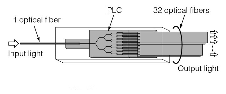
The Structure of PLC splitters

Internal Structure

The following figure shows a PLC splitter. The optical fibre is splitted into 32 outputs. PLC chip is made of silica glass embedded with optical waveguide. The waveguide has three branches of optical channels. When the light guided through the channels, it is equally divided into multiple lights (up to 64) and transmitted via output ports.

1x32-plc-splitter

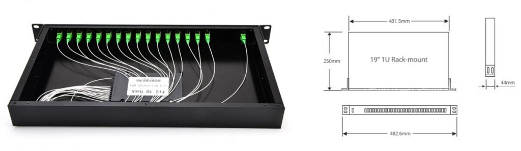
Outside Configuration

Bare splitter is the basic component of PLC fibre splitter. For better protection of the fragile fibre and optimised use, PLC splitters are often equipped with loose tube, connector and covering box. PLC splitters are made in several different configurations, including ABS, LGX box, Mini Plug-in type, Tray type, 1U Rack mount, etc. For example, 1RU rack mount PLC splitter (as shown in the figure below) is designed for high density fibre optical distribution networks. It can provide super optical performance and fast installation. This splitter is preassembled and fibres are terminated with SC connectors. It’s ready for immediate installation.

rack-mount-plc-spllitter

FBT splitters are made by connecting the optical fibres at high temperature and pressure. When the fibre coats are melted and connected, fibre cores get close to each other. Then two or more optical fibres are bound together and put on a fused taper fibre device. Fibres are drawn out according to the output ratio from one single fibre as the input. FBT splitters are mostly used for passive networks where the split configuration is smaller.

PLC Splitters From FS.COM

Fiberstore offers a wide range of PLC splitters that can be configured with 1xN and 2xN. Our splitters are designed for different applications, configurations including LGX, ABS box with pigtail, bare, blockless, rack mount package and so on.

Port Configuration Package Style Fibre Diameter
(Input/output)
Connector (Input/output) Pigtail Length
1×2 Steel tube, bare fibre 250μm None 1.5m
1×4 Mini module 900μm SC APC/UPC 2.0m
1×8 Pigtailed ABS box 2.00mm LC APC/UPC 3.0m
1×16 Mini plugged-in 3.0mm FC APC/UPC Customised
1×32 LGX ST APC/UPC
1×64 Splice Tray Type Customised
2×16 Rack mount
Conclusion

Fibre splitter is an economical solution for PON architecture deployment in FTTH network. It can offer high performance and reliability against the harsh environment conditions. Besides, the small sized splitter is easy for installation and flexible for future network reconfiguration. Therefore, it’s a wise choice to use fibre splitter for building FTTH network.

Comparison Between FBT and PLC Splitters

Enabling a single fibre interface to be shared among many subscribers, fibre optic splitters play an increasingly significant role in many of today’s optical networks. From FTTx systems to traditional optical networks, splitters provide capabilities that help users maximise the functionality of optical network circuits. In this article, I’d like to give a short introduction of fibre optic splitters.

Overview of FBT and PLC Splitters

In simple terms, a fibre optical splitter is a passive optical device that can split, or separate beams into two or more light beams. Based on the configuration of the splitter, these beams may or may not have the equal optical power as the original beam. By means of different constructions, the outputs of a splitter can have varying degrees of throughput, which is highly beneficial when designing optical networks.

fiber optic splitter

Now although technology continually evolves, and there are a variety of existing splitters in the market, the most two common types of fibre optic splitter are: fused biconic tapered splitter (FBT Splitter) and planar lightwave circuit splitter (PLC Splitter).

FBT is the traditional technology in which two fibres are placed closely together and fused together by applying heat while the assembly is being elongated and tapered. As the technology continues developing, the quality of FBT splitter is very good and they can be applied in a cost-effective way. Now FBT is designed to split power in optical telecommunication and widely used in passive networks, especially where the split configuration is relatively small.

FBT splitter.jpg

PLC splitter is a better choice for application where large split configurations are required. It uses an optical splitter chip to divide the incoming signal into multiple outputs. PLC splitter composes of three layers: a substrate, a waveguide, and a lid. The waveguide plays a key role in the splittering process which allows for passing specific percentages of light. Therefore, PLC splitters offer very accurate splits and a low loss. What’s more, PLC splitters have several types such as bare PLC splitter, blockless PLC splitters, fanout PLC splitter, mini-plug in type PLC splitter, etc.

PLC splitter.jpg

With the growth of FTTx worldwide, in order to serve mass subscribers, the demand for large split configurations in these networks has also grown quickly. Because of the performance benefits and overall low cost, PLC splitters are now the better solutions for these types of applications.

FBT Splitter vs. PLC Splitter

In optical networks, signals need to be splitted somewhere in order to serve for different customers. Splitter technology has made great progress in the past few years by introducing PLC splitter. However, being similar in size and outer appearance, the two types of splitter still have many differences. Here is a brief comparison of them.

Materials

FBT splitter is made out of materials that are easily available, for example, steel, fibre, hot dorm and others. All of these materials are cheap, which determines the low cost of the device itself. The technology of the device manufacturing is also relatively simple, which leads to its low prices as well. Compared with FBT splitters, the technology of PLC splitter is more complicated and expensive. It uses semiconductor technology production. Hence it is more difficult to manufacture PLC splitters. And the price of the device is higher.

Operating Wavelength

FBT splitters only supports three wavelengths: 850 nm, 1310 nm and 1550 nm, which makes its inability to works on other wavelengths. While PLC splitter can support wavelength from 1260 to 1650 nm. The adjustable rang of wavelength allows PLC splitter more wide applications.

Split Ratio

The split ratio of FBT splitter is up to 1:32, while the ratio PLC splitter goes up to 64, providing a high reliability. Furthermore, the signal in PlC splitter can be split equally due to technology implemented.

Temperature

In certain areas, temperature can be a crucial factor that affects the performance of optical components. Therefore, sometimes devices with good cold resistance is also vital. FBT splitter can work stable under the temperature of -5 to 75℃. PLC splitter can work at a wider temperature range of -40 to 85 ℃, providing relatively good performance in the areas of extreme climate.

Apart from the differences mentioned above, there are still other differences between FBT splitter and PLC splitter. For example, compared with FBT splitter, the size of PLC splitter is more compact. Hence, PLC spitter is more suitable for density applications.

Conclusion

In conclusion, this article introduce the fibre optical splitters and the differences between FBT splitter and PLC splitter. It’s significant to choose the most suitable splitters for your networks. There are a variety of splitters avaible in Fiberstore. If you want to know detailed information, please visit FS.COM.

How to Ensure a High Quality PLC Splitter?

PLC (Planar Lightwave Circuit) splitter is an important component in PON (passive optical network) where a single optical input is split into multiple outputs. This makes it possible to deploy a Point to Multi Point physical fibre network with a single OLT (optical line terminal) port serving multiple ONTs (optical network terminal). The most common split ratios are 1:N or 2:N. N represents the output ports, usually as 2, 4, 8, 16, etc. The optical input power is distributed uniformly across all output ports. The PLC splitter shares the cost and bandwidth of the OLT and reduces fibre lines. This article will tell about how to keep a high quality PLC splitter from manufacturing to testing sides.

plc-assured-program

Key Manufacturing Steps of PLC Splitter

PLC splitter is composed by many miniature parts. Among them, there are three main components: fibre array for the input and output, and the chip. These three main components decide whether the PLC splitter is of good quality or not. Let’s see the key manufacturing steps of a PLC splitter.

Step1. Components Preparation

The PLC circuit chip is designed and embedded on a piece of glass wafer. Each end of the glass wafer is polished to ensure high precision flat surface and high purity. The V-grooves are grinded into a glass substrate. A single fibre or multiple ribbon fibre is assembled onto the glass substrate. This assembly is polished.

Step2. Alignment

After preparing the three components, it’s time for alignment. The input and output fibre array is set on a goniometer stage to align with the chip. Physical alignment between the fibre arrays and the chip is monitored through the power level output from the fibre array. Epoxy is then applied to the fibre array and the chip to affix their positions.

Step3. Cure

The assembly will be placed in a UV chamber to be fully cured at a controlled temperature.

Step4. Packaging

The bare aligned splitter is assembled into a metal housing where fibre boots are set on both ends of the assembly. A temperature cycling test will be done for a final screening to ensure the final product condition.

Step5. Testing

Optical testing items include insertion loss, uniformity and polarization dependent loss. This testing is to ensure the splitter compliant to the optical parameters in GR-1209 CORE specification.

Testing Standards of PLC Splitter

Then how to determine the quality of a PLC splitter? The GR-1209 standards provides comprehensive optical performance criteria. The following will introduce these specifications such as optical bandpass, insertion loss, return loss, uniformity and directivity.

Optical Bandpass

In a PON system, the downstream transmission uses 1490nm wavelength and 1310nm wavelength for the upstream transmission. Besides, the requirement for RF video overlay and network testing/maintenance should also be considered. The transmission wavelength for RF video is 1550 nm. And the wavelengths for networking testing and maintenance are 1550 nm and 1625 nm. So the standard opterating wavelength for a PON splitter is determined as 1260~1650 nm which covers most of the optical bands.

Insertion Loss

The optical splitter has the largest attenuation in a PON system. The insertion loss transfers from the input port to the output port. In order to conserve the power of a PON system, the insertion loss should be reduced to the least. There are formulas to calculate the maximum insertion loss of an optical splitter in a PON system according to the GR-1209 standard: 0.8 + 3.4 log2N (for 1xN optical splitter) and 1.0 + 3.4 log2N. To decide if the insertion loss is in the qualified range, you need to choose one formula to calculate.

Return Loss

Optical return loss is part of the power transferred from one input port back to the same input port or from an output port back to the same output port. A high return loss will influence the data transmission quality. So it’s important to minimize the noise to keep the PON system power for a better transmission.

Uniformity

Uniformity means the maximum insertion loss value between one input port and any two output ports or between two input ports and one output port. This can ensure that the transmission power at each splitter output port is the same in a PON system to simplify the network design.

Directivity

Directivity is the part of power transferred from one input port to another input port or from an output port to another output port. For a 2xN optical splitter, when light injects into one of the input ports, light doesn’t only propagate out of the output ports. Some of the light propagates back through the second input port. And when the light injects into one of the output ports, light propagates back through the other output ports. In a bidirectional transmission system such as a PON, directivity is useful to reduce signal crosstalk. A high directivity value will increase the insertion loss due to the optical power loss.

Conclusion

FS.COM provides a variety of PLC splitters including 1×2, 1×4, 1×8, 1×16, 1×32, 1×64; 2×2, 2×4, 2×8, 2×16, 2×32, 2×64 in various package options, which offer cost-effective solutions for your applications. To ensure high performance, we have set a quality assurance program for PLC splitter. We always care every detail both in manufacture and testing. For detailed information, please contact us via sales@fs.com.

EPON vs. GPON—Which Will Be More Popular?

With the development of passive optical networking (PON) technology, two PON standards are striking in FTTH solution area and they are Ethernet passive optical networking (EPON) and ATM (asynchronous transfer mode)-based Gigabit passive optical networking (GPON). During these years, it has become a hot topic that which will be more popular in broadband access and optical telecom applications, EPON or GPON? This article will compare these two technologies from the differences of architecture, bandwidth, efficiency, cost, etc.

Architecture

The biggest difference between the two technologies shows in architecture. EPON employs a single Layers 2 network that uses IP to carry data, voice, and video. While GPON provides three Layer 2 networks: ATM for voice, Ethernet for data, and proprietary encapsulation for voice.

EPON-and-GPON

EPON provides seamless connectivity for any type of IP-based or other “packetised” “communications”. Since Ethernet devices are so popular and easy to get, implementation of EPONs can be highly cost-effective.

In GPON, virtual circuits are provisioned for different kinds of services sent from a central office primarily to business end users. This kind of transport provides high-quality service, but includes significant overhead because virtual circuits should be provisioned for each type of service. GPON equipment requires multiple protocol conversions, segmentation and reassembly (SAR), virtual channel (VC) termination and point-to-point protocol (PPP).

Bandwidth

EPON delivers symmetrical bandwidth of 1 Gbit/s. EPON’s Gigabit Ethernet service actually constitutes 1 Gbit/s of bandwidth for data and 250 Mbit/s of bandwidth for encoding. GPON promises 1.25-Gbit/s or 2.5-Gbit/s downstream, and upstream bandwidths scalable from 155 Mbit/s to 2.5 Gbit/s. GPON’s 1.25-Gbit service specifies a usable bandwidth of 1.25 Gbit/s, with no requirement for encoding. Gigabit Ethernet interfaces to the aggregation switch, central office, and metro are currently cost-effective to aggregate 1-Gbit ports for transport. But for 1.25 Gbit, there is no way.

Efficiency

Efficiency has to be considered in both directions of a PON. Each PON protocol introduces its own overhead in either direction. In the downstream direction, protocol overhead could be negligible. In the upstream direction, the total scheduling overhead within EPON is from 90.33 percent to 97.08 percent compared to a GbE point-to-point link. In the downstream direction, EPON efficiency reaches from 97.13 percent to 98.92 percent of the efficiency of a point-to-point 1GbE link, while GPON in GTC Encapsulation Method (GEM) mode can achieve ~ 95 percent efficiency of its usable bandwidth. The downstream EPON data rate can be doubled to 2.5Gbps comparable to GPON.

Cost

EPON simplifies the networks and needs no complex and expensive ATM and Sonet elements. Thus it helps lower the costs to subscribers. Now the cost of EPON equipment is about 10 percent of the costs of GPON equipment.

Encryption

Encryption is part of the ITU standard. EPON uses an AES-based mechanism, which is supported by multiple silicon vendors and deployed in the field. And EPON encryption is both downstream and upstream. However, GPON encryption is downstream only.

Ethernet Features

EPON is an IEEE Ethernet standard and uses Ethernet switches within its silicon, it can natively support all of the 802.1 and 802.3 Ethernet, including VLAN tags, prioritisation, OAM, etc. All Ethernet services can be natively delivered in a manner identical to what is done with switched Ethernet today. As to GPON, it only defines the transport of Ethernet frames. So it has no native Ethernet functionality. Ethernet switches must be placed either in front of or within GPON OLTs and ONTs to provide any additional Ethernet capabilities.

EPON and GPON technologies have been introduced into the market because of service quality and price point. By comparing the differences of the two technologies, it shows EPON is a superior technology for delivering residential and small-to-medium enterprise Ethernet services in terms of its advantages in bandwidth, efficiency, cost, encryption and Ethernet features. So EPON will be employed in FTTH solution area in a large scale earlier and faster than GPON.

Originally published at http://www.streetarticles.com/internet-and-businesses-online/epon-vs-gponwhich-will-be-more-popular

How FTTH Broadband Works?

Stop and think how your Internet usage has evolved during the last few years. If you’re like most people, you will do, and looking forward to more online interaction, such as increasing rich media and upload and download images and video.

More large files are moving across the cyberspace network these days, and experts expect that trend will only increase. In January 2008, the study by the Discovery Institute estimates new technologies will drive Internet traffic up by 50 times its current rate within the next 10 years.

The pressure for better connectivity is one of the main reasons providers and users to view its fibre to the home broadband connections as a potential solution.

FTTH broadband connections, refer to optical fibre cable connection for individual residences. Such optical based system can provide large amounts of digital information, telephone, video, data, and so on, more efficiently than traditional copper coaxial cable for about the same price. FTTH premises depend on both active and passive optical networks to function.

FTTH network cables connection is a reality of more than 1 million consumers in the United States, and more than 6 million Japanese and 10 million global to enjoy its benefits, broadband property according to the magazine. Many people think that the FTTH technology standard to predict network connection can solve traffic congestion.

More than 10 million homes worldwide already have fibre to the home broadband connections because the technology holds many advantages over current technologies.

What are the advantages to FTTH broadband connections?

A key advantage to FTTH – also called FTTP, for “fibre to the premises” broadband – is that it provides for far faster connection speeds and carrying capacity than twisted pair conductors, DSL or coaxial cable. Experts at the FTTH Council say fibre-to-the-home connections are the only technology with enough bandwidth to handle projected consumer demands during the next decade reliably and cost effectively. The technology is already, affordable, as businesses around the world are demonstrating by getting into the business as they speculate on consumer demand.

Fibre has a virtually unlimited bandwidth coupled with a long reach, making it “future safe,” or a standard medium that will be in place for a long time to come.

However, greatly improving the bandwidth cost and current technology. According to the FTTH Council, cable companies spent about $84 billion to line family ten years ago, but it costs less in today’s dollars line those houses with FTTH technology.

FTTH will be able to handle even the future Internet use some experts see the future. Technologies such as 3D holographic high definition television and games will one day become daily necessities of families all over the world. FTTH will be able to handle estimated 30-gigabyte-per-second needs of such equipment.

Active and Passive Optical Networks

There are two important types of systems that make FTTH broadband connections possible. These are active optical networks and passive optical networks. Each offers ways to separate data and route it to the proper place, and each has advantages and disadvantages as compared to the other.

An active optical system uses electrically powered switching equipment, such as a router or a switch aggregator, to manage signal distribution and direct signals to specific customers. This switch opens and closes in various ways to direct the incoming and outgoing signals to the proper place. In such a system, a customer may have a dedicated fibre running to his or her house.

A passive optical network, on the other hand, does not include electrically powered switching equipment and instead uses optical splitters to separate and collect optical signals as they move through the network. A passive optical network shares fibre optic strands for portions of the network. Powered equipment is required only at the source and receiving ends of the signal.

Active and Passive Optical Networks of the advantages and disadvantages

Passive optical networks, or PONs, have some distinct advantages. They’re efficient, in that each fibre optic strand can serve up to 32 users. PONs have a low building cost relative to active optical networks along with lower maintenance costs. Because there are few moving or electrical parts, there’s simply less that can go wrong in a PON.

Passive optical networks also have some disadvantages. They have less range than an active optical network, meaning subscribers must be geographically closer to the central source of the data. PONs also make it difficult to isolate a failure when they occur. Also, because the bandwidth in a PON is not dedicated to individual subscribers, data transmission speed may slow down during peak usage times in an effect known as latency. Latency quickly degrades services such as audio and video, which need a smooth rate to maintain quality.
Active optical networks offer certain advantages, as well. Their reliance on Ethernet technology makes interoperability among vendors easy. Subscribers can select hardware that delivers an appropriate data transmission rate and scale up as their needs increase without having to restructure the network.

Active optical networks, however, also have their disadvantages. They require at least one switch aggregator for every 48 subscribers. Because it requires power, an active optical network inherently is less reliable than a passive optical network.