Category Archives: Fiber Testers & Tools

Fusion Spilcer

Fiber fusion splicer is a device used to join two optical fibers end-end by fusion (sometimes called welding or heating). By using an electric arc, two optical fibers can be melted together at their end faces, forming a single long fiber. The source of heat is usually an electric arc, but can be a laser, or a gas flame and so on. And the resulting joint, or fusion splice, permanently joins the two glass fiber end to end so that optical light can pass from one fiber into the other with very little loss.

As an dispensable tool for fiber outside plant (OSP) and indoor cable network installation, fiber fusion splicers are widely used in optic network installation. A long-haul and high-capacity fusion splicer can splice optical fibers of high performance , helping establish a low-loss and high-speed telecommunication line. Contributing in telecommunications, medical application, image progress, energy research where light matters, those splicers have an great influence on connecting optical fibers with superior precision to ensure data are transmitted reliably anywhere.

0e23e1a280.image.550x550

According to different splicing technologies, fiber fusion splicers can be classified into three types: core alignment splicer, ribbon fiber fusion splicer and special fiber fusion splicer.

Core Alignment Fusion Splicer
It is mostly used in the world. With optical fiber aligned by a movable v-groove alignment mechanism and heated by electric discharge between tungsten electrodes, these fiber splicers can measure core position with high accuracy.

Ribbon Fusion Fiber Splicer
It is an essential tool to enhance work efficiency in the case ribbon fibers are applied. since each pitch of fiber is as narrow as 250um on ribbon fiber, it is difficult to apply movable v-grooves for each fiber. Thus, fixed v-groove is used for ribbon fiber splicing which can shorten the operation time for ribbon fiber fusion splicer is spliced all at once.

Special Fiber Fusion Splicer
It has developed an adjustable fiber clamping position mechanism, electrode oscillating mechanism, and optical fiber end-view image observation system in order to splice various types of fibers, such as polarization maintaining fibers and large diameter fibers for high power laser transmission.

In recent years, as optical fiber has been connected to homes, demand of compact and light fusion splicers are rising. Fusion splicers are been updating into smaller and lighter ones with higher capacity, lower loss and greater productivity instead of big, heavy and, expensive and easily damaged old ones. For instance, Fujikura, the leading splicer brand in the world, has developed a comprehensive range of fusion splicer products to cater for every application in the last 30 years. It lately has invented  the FSM-80S alignment fusion splicer succeeding to FSM-60S. The 80S has a series of new features, such as ” Automated wind-protector and tube-healer” for quicker splicing cycle as well as fewer operation steps, “innovative carrying-case design” for quicker preparation and so on. It is obvious that it has plenty of advantages over older ones in many aspects. Fiberstore offers all kinds of fusion splicers with high quality. Welcome to visit our website and get more information.

Things You Shoud Know about Fiber Optic Cleaning

Fiber optic cleaning is one of the most basic and important procedures for the maintenance of fiber optic systems. Its goal is to keep all optical connections free of contaminants to avoid losses caused by dirt, dust and other contaminants, ensuring a high-speed data transmission over optical fibers. This post aims to introduce some of the useful fiber optic cleaning tools and give some tips on fiber optic cleaning process.

Tools of Fiber Optic Cleaning
A wide variety of fiber optic cleaners are provided to complete the cleaning procedure, such as push-type cleaners, reel-type cleaners, wipes and cleaning cards, cleaning sticks, tips and swabs and so on. Because a good fiber optic cleaning will need all kinds of these tools. Thus, many vendors offer the fiber cleaning kits which consist of all kinds of tools to meet customers’ specific application needs with high efficiency of cleaning end-faces. Here we are going to introduce some commonly used fiber optic cleaning tools.下载

Push-type cleaners are equipped with an easy one push action which quickly and effectively clean the end-face of connectors on jumpers or through adapters. It is one of the useful ways to clean connectors and maximize network performance with a low cost. Reel-type cleaner are designed to clean a variety of connectors. They are safe cleaning options without the need for alcohol, which can be toxic and flammable. And their refillable cleaning tapes making them ideal for lab, assembly lines and field use. Wipes and Cleaning Cards are also the indispensable tools designed to be used dry or with cleaning fluid for effectively removing common contaminants from optical jumpers and parch cords. Cleaning sticks, Tips and Swaps are specifically intended for cleaning fiber optic connector end-faces.

Tips For Fiber Optic Cleaning
Cleaning Methods
Fiber optic cleaning kits, containing above tools, can be divided to four types based on different cleaning methods: dry cleaning, wet cleaning, abrasive cleaning and non-abrasive cleaning. Drying cleaning is a kind of way in which optic cleaning use no solvent. For instance, air spray, lint free wipes, reel based fiber connector cleaner, cletop stick and so on are all dry cleaning products ideal for cleaning transceiver ports. However, wet cleaning is conducted on the opposite way. Products such as alcohol with lint-free wipes and pre-saturated or soaked wipes use a solvent to clean. And the other two cleaning methods are abrasive cleaning and non-abrasive cleaning classified by whether the abrasive material touching the fiber optic connector end-face.

Cleaning Procedures
In order to make sure that you do a good job of fiber optic cleaning, you are required to complete following steps when cleaning.

  • Inspect the fiber connector, component, or bulkhead with a fiberscope. If the connector is dirty, clean it with a dry cleaning technique.
  • Inspect the connector. If the connector is still dirty, repeat the dry cleaning technique.
  • Inspect the connector. If the connector is still dirty, clean it with a wet cleaning technique followed immediately with a dry clean in order to ensure no residue is left on the end-face. (Note: Wet cleaning is not recommended for bulkheads and receptacles. Damage to equipment can occur.)
  • Inspect the connector again. If the contaminate still cannot be removed, repeat the cleaning procedure until the end-face is clean.

For more information of fiber optic cleaning and fiber optic cleaning tools, please visit fs.com or contact us over sales@fs.com.

What factors will affect the fiber splicing result?

I get the answer from a professional fiber splicing engineer- William Graham

He tell that:

1 Keep the fiber splicer and fiber cleaver in the case when not in use.

2 Be sure you are set on the proper splicing program for the fiber you are splicing.

3 Don’t expect good splices under adverse conditions of dirt, dampness and wind. Create good splicing conditions.

4 Keep the dome and heater covers closed unless you are splicing or heating

5 Close the cleaves as soon as you take out the cleaved fiber

6 Clean your splicer before you start splicing.

7 Use an air bulb and fine brush for cleaning.

8 Do not used spray cans or the propellants might do damage.

9 If splicing gel filled cable ensure it is really clean so you don’t gum up the splicer.

10 Clean any gummed up grooves with a piece of sharp wood. Never use metal.

11 Charge the battery when you finish. The splicer we use will do over 200 splices and heats on a charge.

12 Have a stable and secure place for your splicer when splicing. If it drops on the floor it is probably garbage.

13 Keep your shrink splice sleeves in a sealed container (ziplock bag)

14 If you drop the shrink splice sleeve on the floor, leave it there.

15 Never clean the fiber with alcohol after you have cleaved it or you might cause reflections.

16 Have the splicer serviced (calibrated) when necessary

17 Clean the cleaver before you start with a fine brush and alcohol, especially if using gel filled cable.

18 Close the cleaver between cleaves to keep out air-borne dirt.

19 And, finally, if you drop the cleaver on the floor its value will be drastically diminished.

Manage your fiber ends and empty the scrap container at the end of the day.

Do the splice job as above points, you will get a good splice. Additionally, I also have a write a tutorial about fiber splicing process. You can read all from here. http://www.fs.com/Optical-Fusion-Splicing-Tutorial-aid-350.html and if you need fiber optic jumpers also can sent requriments to sales@fs.com

Understanding Fiber Optic Based Light Source

Each piece of active electronics will have a variety of light sources used to transmit over the various types of fiber. The distance and bandwidth will vary with light source and quality of fiber. In most networks, fiber is used for uplink/backbone operations and connecting various buildings together on a campus. The speed and distance are a function of the core, modal bandwidth, grade of fiber and the light source, all discussed previously. Light sources of the fiber light source are offered in a variety of types. Basically there are two types of semiconductor light sources available for fiber optic communication – The LED sources and the laser sources.

Using single mode fiber for short distances can cause the receiver to be overwhelmed and an inline attenuator may be needed to introduce attenuation into the channel. With Gigabit to the desktop becoming commonplace, 10Gb/s backbones have also become more common. The SR interfaces are also becoming common in data center applications and even some desktop applications. As you can see, the higher quality fiber (or laser optimized fiber) provides for greater flexibility for a fiber plant installation. Although some variations ( 10GBase-LRM SFP+ and 10GBASE-LX4) support older grades of fiber to distances 220m or greater, the equipment is more costly. In many cases, it is less expensive to upgrade fiber than to purchase the more costly components that also carry increased maintenance costs over time.

Light sources of the fiber light source are offered in a variety of types. Basically there are two types of semiconductor light sources available for fiber optic communication – The LED sources and the laser sources.

In fiber-optics-based solution design, a bright light source such as a laser sends light through an optical fiber, called laser light source . Along the length of the fiber is an ultraviolet-light-treated region called a “fiber grating.” The grating deflects the light so that it exits perpendicularly to the length of the fiber as a long, expanding rectangle of light. This optical rectangle is then collimated by a cylindrical lens, such that the rectangle illuminates objects of interest at various distances from the source. The bright rectangle allows line scan cameras to sort products at higher speeds with improved accuracy.

The laser fiber-based light source combines all the ideal features necessary for accurate and efficient scanning: uniform, intense illumination over a rectangular region; a directional beam that avoids wasting unused light by only illuminating the rectangle; and a “cool” source that does not heat up the objects to be imaged. Currently employed light sources such as tungsten halogen lamps or arrays of light-emitting diodes lack at least one of these features.

What Is Visual Fault Locator and How to Use It

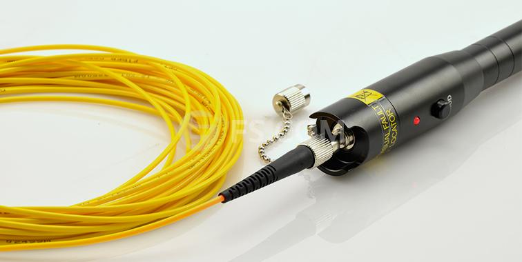
The Fibre Fault Locator (VFL) is an essential tool for every Fibre Termination Kit. It is like the continuity tester. The VFL is not one of the least expensive tools in your tool kit. It will allow you to quickly identify breaks or macrobends in the optical fibre, and identify a poor fusion splice in multimode or single-mode optical fibre.

fs-visual-fault-locator

The big difference between the VFL and the continuity tester is the light source and optical output power of the light source. The VFL typically uses a red (635-650nm) laser light source. The optical output power of the laser is typically 1mW or less. Because of the high optical output power, you should never view the output of the VFL directly.

The Visual Fault Locator is available in different shapes and sizes. Some may look like a pen. Others may be built into an optical time domain reflectometer (OTDR), and some may look like a small test equipment box. There are two types of VFLs: contact and non-contact. With a contact VFL, the optical fibre under test will make contact with the VFL. However, with a non-contact VFL the optical fibre under test will not touch the VFL.

Unlike the continuity tester, the VFL is not limited to testing multimode optical fibres 2km or less in length. The VFL can be used to verify continuity of multimode or single-mode optical fibre longer than 2km. Due to attenuation of the 635–650nm laser light source by the optical fibre, macrobends may not be detectable beyond 1km in multimode optical fibre and 500 metres in single-mode optical fibre. The same holds true for finding breaks in the optical fibre through the jacket of the fibre-optic cable.

How to Use Visual Fault Locator

As with the continuity tester, the first thing you will need to do is clean the connector endface and inspect it with a microscope. If the endface finish is acceptable, the VFL can be connected to a Optical Fibre Connectors should not be viewed directly during this testing.

The VFL fills the core of the optical fibre with light from the laser. The light from the laser escapes the optical fibre at a break or macrobend. The light escaping from the optical fibre will typically illuminate the buffer surrounding the optical fibre. Macrobends are not always visible through the jacket but are typically visible through the buffer. Breaks may be visible through the jacket of the fibre optic cable depending on jacket color, thickness, number of optical fibres in the cable, and amount of strength member.

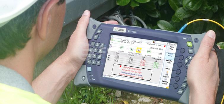
The VFL and the fibre OTDR work hand in hand with each other when it comes to locating breaks in an optical fibre. The OTDR can provide the operator with the distance the break. The VFL allows the operator to see the break in the optical fibre.

jdsu-otdr

Fibre optic cables are not the only place where the optical fibre may break. The optical fibre may break inside the connector or connector ferrule. Unless the optical fibre is broken at the endface of the connector, it is not visible with a microscope.

Usually, students connect cables that look great when viewed with the microscope but fail continuity testing. When this happens, the hardest part is determining which connector contains the break in the optical fibre. Without a VFL in the classroom, students would have to cut the cable in half and use the continuity tester to identify the bad connection.

The VFL will often identify the bad termination or connector.  Looking at the photograph, you can see VFL illuminating the break in the optical fibre. The output of the VFL is so powerful that it penetrates the ceramic ferrule.

The visual fault locator can be used to test the continuity of an optical fibre in the same manner. The first step when using the continuity tester is to clean and visually inspect the end face of the connector before inserting it into the continuity tester. After the connector has been cleaned and inspected, you need to verify that the continuity tester is operating properly. Turn the continuity tester on and verify that it is emitting light.

The visual fault locator also can be used to locate a macrobend in an optical fibre. However, macrobends do not allow nearly as much light to penetrate the buffer and jacket as does as break in the optical fibre. Locating a macrobend with the VFL may require darkening the room.

Macrobends and high loss fusion splices appear the same on an OTDR trace. The VFL allows the identification of a high-loss fusion splice.

Cable Testing With Fluke Cable Tester

No matter installing new cable, or troubleshooting the existing cable, cable testing plays an essential role in the process. Common tests for datacom cabling include length, wiremap, attenuation, NEXT, DC loop resistance, and return loss. When doing cable testing must with the Fibre Tester, and the Fluke Network Cable Tester is popular.

As networks evolve, so do the requirements of the cabling infrastructure to support them. New standards are continuously being developed to provide guidelines for cabling professionals when installing, testing, troubleshooting, and certifying either copper and fibre. Whether it’s 10BASE-T, 100BASE-TX or 1000BASE-T, there are specific requirements and potential pitfalls in implementing these technologies. And 10GBASE-T, it becomes even more critical to keep current with the latest proliferations in cabling and cable testing.

Cable testing provides a level of assurance that the installed cabling links provide the desired transmission capability to support the data communication desired by the users. Cable test instruments are designed with a variety of focused features for particular field tasks. They vary in price, performance, and application.

For example, there are typically two types of tools for checking network connectivity: the network tester tool and the Fluke tester. Sometimes an engineer will carry a noise generator which not only checks ethernet networks but also telephone lines. Network tester tool is the network checker which plugs directly into the line and reads out what line is connected on that drop, or if there is no signal there. This can also be done with a laptop computer, but it is easier to carry a network tester, since it is far smaller. The Fluke tester will read all four twisted pairs of a cable right from the drop at the workstation all the way back to the server room and will show exactly which pairs are good and if any are crossed or open. The engineer can put a noise on the line and trace it back to the complex loom of cables in the server room all arriving in the same area at the main switch or patch panel.

Verification test tools perform basic continuity functions, they assure that all wires in a cabling link are connected to the proper termination points and not to any other conductors. In twisted pair cabling, it is critical to maintain the proper pairing of the wires. Better verification test tools also verify wire pairing and detect installation defects like “split pairs”. Verification test tools may also assist in troubleshooting by providing a toner to locate a cabling link. Verification tools sometimes include additional features such as an Fibre OTDR to determine length of a cable or distance to a break or short circuit. These test tools do not provide any information on bandwidth or suitability for high-speed data communication.

Punch Down Tool of Network Cabling Tools

A punch down tool (also known as punch down tool or krone tool) is needed to quickly and efficiently connect cable wires to electrical contacts. Not only do these tools make faster connections, but because many connecting blocks like 66-type or 110-type are designed for use with these punch down tools.

It’s not only a Network Cable Crimper for terminating Cat 5, Cat 5e or Cat 6 cables, but it also will punch down a 110 IDC RJ45 jack. It’s a quality piece of equipment. To successfully create Ethernet jacks that computers connect to and for terminating Ethernet cables in a way that does not impair the data signal, IT workers need the right tools. Crimpers are used to terminate RJ45 heads—the little plastic plugs that allow an Ethernet cable to fit either into an RJ45 wall jack or the Ethernet port on a computer. Crimpers that did not have the right amount of pressure to make a good crimp as well as the sometimes-flimsy punch down tool that comes with RJ45 jacks—making wiring time-consuming and frustrating.

Common Features of Punch Down Tools

Typical on the market there are three different punch down tools available, including standard impact tool, universal automatic impact tool and corrosion resistant termination tool. Most punch down tools are of the impact type, consisting of a handle, an internal spring mechanism, and a removable slotted blade. They typically are 6-8 inches long with a blade at one end. The top and bottom of the tool are usually different colors to help users identify which side is used to cut the wire. Most models have a changeable blade and a pressure adjustment screw or knob.

The dimensions of the punch down tool are not standardized. Some tools measure 5.35 in x 1.06 in x 1.06 in and weigh 4.69 oz. Others have dimensions of 5.25 in x 1.26 in x 1.26 in, 7.00 in x 2.02 in x 2.02 in and so on. Their weights also vary. Whatever the dimensions of the punch down tool are, usage is the same.

How to Use a Punch Down Tool?

1. Prepare to punch down a wire.
Standing in front of the connection block, hold the punch down tool in one hand, with the cutting blade facing down. Hold the wire in your other hand and loop it through the selected connection block terminal.

2. Punch down the wire.
Holding the end of the wire firmly, place the blade of the punch down on the selected connection terminal and push forward until you reach the bottom of the terminal. Continuing to hold the end of the wire, punch the tool firmly with a straight-forward motion. If done correctly, this action should connect the wire to the terminal and cleanly cut off any excess.

3. Check your connection.
Make sure your connection is secure and there is no loose or broken wire left in the connection block. Tug on the wire to verify that it is securely fastened and connected to the correct terminal.

There are many types of punch down tools available and have different features. The good ones will have reversible blades. This can be handy in many instances. It is also important for the blade to fit in properly. The tool must also be robust. Find other fiber optic tools at Fiberstore.

Maintance Methods Of Fusion Splicer Parts

The most common parts of a fibre fusion splicer include Electrodes and V-Grooves. Fusion splicers are dependent upon high-quality electrodes to focus that critical arc of electricity. As the electrodes wear from use, electrodes gradually worn and lead to weaker splices and higher splice losses. Cleaning electrode is part of the essential maintenance of fusion splicer and will not restore the performance of the fusion splicer as electrodes need to be replaced.

Always replace fusion splicer electrodes as a pair. For optimal performance, electrodes should also be aligned when they are replaced. This is a tuning process to maximise the performance of your splicer.

The Maintance Methods Of Fibre Fusion Splicer Parts:

1. Electrical welding electrode life is generally about 2000, after a long time the electrode will be oxidized, resulting in the discharge current is too large leaving the splice loss value increases. You can remove the electrodes, medical cotton wool dipped in alcohol to gently wipe and then install the fusion splicer, and discharge cleaned once. If repeated washing, the discharge current is still too large, it shall replace the electrode.

Replace the electrode first remove the protection of the electrode chamber cover, loosen the screws fixed on the electrode, remove the upper electrode. Then release the top wire fixed to the lower electrode, remove the lower electrode. Installation of new electrode opposite action of the demolition order, require two electrode tip clearance: 2.6 ± 0.2mm, with the optical fibre symmetry. Under normal circumstances electrode is not required to be adjusted. Not touch the tip of the electrode in the replacement process, prevent damage, and should avoid the electrodes to fall inside the machine. After replacing the electrode to carry out calibration of the arc position.

Care of the electrode used for a long time, the tip of the electrode will produce sediment discharge poor, then there will be a “hissing” sound, then need to clean the electrode. The recommended the regular welding machine electrodes care that clean the electrode.

2. 4 clean V-shaped groove welding machine tune the core direction of the upper and lower driving range each only tens of microns, slightly foreign body will make the fibre image deviation from the normal position, resulting in normal alignment. At this time the need for timely clean the V-groove:

a. Off the windshield of the welding machine.

b. Open the fibre optic pressure head and the clamping platen.

c. Stick with a cotton swab dipped in anhydrous alcohol (or sharpened toothpick) single wipe in a V-Groove Fibre Aligner.

Note: Avoid using hard objects to clean the V-groove or V-groove on the force, to avoid bad V-groove or V-groove inaccurate, resulting in the instrument can not properly use.

Proper use of Fusion Splicer is to reduce an important guarantee of the optical fibre splice loss and key links. You always should be strictly in accordance with the instructions of the welding machine and operational procedures. And properly set the welding parameters according to the type of fibre (including pre-discharge current, time and the main discharge current, the main discharge time). Do as above, the working life of your fusion splicer certain can be longer.

Choose The Right Fibre Optic Tools For Cable Splicing And Terminating

Correctly splicing and terminating fibre optic cable requires special tools and methods. Training is essential and there are many excellent causes of training available. Do not mix your electrical tools with your fibre tools. Use the right tools to do the job! Being experienced in fibre work will end up increasingly necessary because the importance of data transmission speeds, fibre towards the home and fibre to the premise deployments still increase.

Many factors set fibre installations apart from traditional electrical projects. Fibre optic glass is very fragile; it’s nominal outside diameter is 125 micron. The slightest scratch, mark or perhaps speck of dirt will affect the transmission of light, degrading the signal. Safety factors are important because you will work with glass that can sliver to your skin without being seen through the human eye. Transmission grade lasers are extremely dangerous, and require that protective eyewear is a must. This industry has primarily been coping with voice and data grade circuits that may tolerate some interruption or slow down of signal. The person speaking would repeat themselves, or even the data would retransmit. Today we are dealing with IPTV signals and customers who’ll not tolerate pixelization, or momentary locking from the picture. All the situations mentioned are reason for the client to look for another carrier. Each situation might have been avoided if proper attention was handed towards the techniques used when preparing, installing, and maintaining fibre optic cables.

Jacket Strippers are utilized to remove the 1.6 – 3.0mm PVC outer jacket on simplex and duplex fibre cables. Fibre Cutters will cut and trim the kevlar strength member directly underneath the jacket and Buffer Strippers will take away the acrylate (buffer) coating from the bare glass. A protective plastic coating is used to the bare fibre after the drawing process, but just before spooling. The most typical coating is really a UV-cured acrylate, that is applied in two layers, producing a nominal outside diameter of 250 micron for that coated fibre. The coating is highly engineered, providing protection against physical damage caused by environmental elements, such as humidity and temperature extremes, contact with chemicals, reason for stress… etc. whilst minimizing optical loss. Without it, the manufacturer wouldn’t be in a position to spool the fibre without breaking it. The 250 micron-coated fibre may be the building block for a lot of common fibre optic cable constructions. It is usually used as is, particularly when additional mechanical or environmental protection is not needed, for example inside of optical devices or splice closures. For additional physical protection and easy handling, a secondary coating of polyvinyl chloride (PVC) or Hytrel (a thermoplastic elastomer that has desirable characteristics to be used as a secondary buffer) is extruded within the 250 micron-coated fibre, increasing the outside diameter as much as 900 micron. This kind of construction is called ‘tight buffered fibre’. Tight Buffered may be single or multi fibre and are observed in Premise Networks and indoor applications. Multi-fibre, tight-buffered cables often can be used for intra-building, risers, general building and plenum applications.

‘Loose tube fibre’ usually includes a bundle of fibres enclosed inside a thermoplastic tube referred to as a buffer tube, which has an inner diameter that is slightly larger than the diameter of the fibre. Loose tube fibre has a space for the fibres to grow. In a few climate conditions, a fibre may expand after which shrink over and over again or it may be exposed to water. Fibre Cables will sometimes have ‘gel’ within this cavity (or space) yet others that are labeled ‘dry block’. You will find many loose tube fibres in Outside Plant Environments. The modular design of loose-tube cables typically stands up to 12 fibres per buffer tube with a maximum per cable fibre count in excess of 200 fibres. Loose-tube cables can be all-dielectric or optionally armored. The armoring is used to protect the cable from rodents such as squirrels or beavers, or from protruding rocks in a buried environment. The modular buffer-tube design also permits easy drop-off of categories of fibres at intermediate points, without disturbing other protected buffer tubes being routed to other locations. The loose-tube design also helps in the identification and administration of fibres within the system. When protective gel is present, a gel-cleaner such as D-Gel will be needed. Each fibre will be cleaned with the gel cleaner and 99% alcohol. Clean room wipers (Kim Wipes) are a good choice to use with the soap. The fibres inside a loose tube gel filled cable will often have a 250 micron coating so that they tend to be more fragile than the usual tight-buffered fibre. Standard industry colour-coding can also be accustomed to identify the buffers along with the fibres in the buffers.

A ‘Rotary Tool’ or ‘Cable Slitter‘ can be used to slit a diamond ring around and thru the outer jacketing of ‘loose tube fibre’. Once you expose the durable inner buffer tube, you can use a ‘Universal Fibre Access Tool’ that is designed for single central buffer tube entry. Utilized on the same principle because the Mid Span Access Tool, (which allows access to the multicoloured buffer coated tight buffered fibres) dual blades will slit the tube lengthwise, exposing the buffer coated fibres. Fibre handling tools such as a spatula or perhaps a pick can help the installer to access the fibre in need of testing or repair. Once the damaged fibre is exposed a hand- stripping tool will be used to take away the 250 micron coating in order to work with the bare fibre. The next step is going to be cleaning the fibre end and preparing it to be cleaved. A great cleave is among the most important factors of manufacturing a low loss on the splice or a termination. A Fibre Optic Cleaver is really a multipurpose tool that measures distance in the end of the buffer coating enough where it will likely be joined also it precisely cuts the glass. Always remember to utilize a fibre trash-can for that scraps of glass cleaved from the fibre cable.

When performing fusion splicing you may need a Fusion Splicer, fusion splice protection sleeves, and isopropyl alcohol and stripping tools. If you are using a mechanical splice, you will need stripping tools, mechanical splices, isopropyl alcohol and a mechanical splice assembly tool. When hand terminating a fibre you will need 99% isopropyl alcohol, epoxy/adhesive, a syringe and needle, polishing (lapping) film, a polishing pad, a polishing puck, a crimp tool, stripping tools, fibre optic connectors (or splice on connectors) and piano wire.

Whenever a termination is complete you have to inspect the finish face of the connector having a Fibre Optic Inspection Microscope. Ensuring light is getting most likely through the splice or even the connection, a visible Fault Locator may be used. This piece of equipment will shoot a visible laser down the fibre cable so you can tell there are no breaks or faulty splices. If the laser light stops on the fibre somewhere, there’s most likely a break in the glass at that point. If you find more than a dull light showing in the connector point, the termination was not successful. The light should also pass through the fusion splice, if it does not, stop and re- splice or re-terminate.
Fiberguide Can Provide Fiber Optic Retail And Local Inventory Service


Summarize

With the requirement of the high energy laser and special fiber optical sensing application market has become increasingly active in China market, more and more customers need to use small quantities (<20m) of fiber to carrying research and development test, mass production until the system pass the verification assessment.

FiberStore news, US-based specialty fiber solutions provider Fiberguide had announced that it can provide RMB settlement, fiber optic retail and local inventory and other services.

With the requirement of the high energy laser and special fiber optical sensing application market has become increasingly active in China market, more and more customers need to use small quantities (<20m) of fiber to carrying research and development test, mass production until the system pass the verification assessment. It requires international fiber optic providers to be more flexible and respond more quickly. Fiberguide, comply with the requirements of customers, has been completed the whole work of RMB settlement  and fiber optic products local stocks, fiber can be sold by meter, always running stock fiber optic products and delivery within one week after payment.

Providing fiber retail and local inventory are important parts of Fiberguide’s work plan in Chinese market. The first regular standing fiber will include the Polyimide high-temperature fiber whose temperature can reach up to 350��, as well as Japanese double-clad high power fiber (size 200/500/780/1300, 300/500/780/1300, 400/500/780/1300) and so on. Fiberguide will timely add more varieties of fiber based on customer feedback.

The first batch of domestic customers purchasing retail specialty fiber is gold plated. Fiberguide believes that hot sale products will be Japanese double-clad high-power fiber and single-use medical fiber which are widely used in the market, relevant preparation work is carrying on in order.