Category Archives: Fiber Testers & Tools

MPO Cables Testing Method

As the migration to 40G/100G Ethernet using parallel array transmission systems, the high-density MPO cables are widely used in the data centre. In the connection, contamination even as small as 0.001 mm can cause the optical loss. Mating a contaminated connector to a clean connector will lead to poor performance and can damage the connection. So it’s important to test the link segments consisting of MPO array cabling and keep the cable clean. However, MPO cable testing and cleaning is full of challenges.

Why MPO cable testing and cleaning is not easy? First, MPO connectors are very sensitive to dirt and contamination. The ferrules are large and hard to clean and inspect. Most microscopes don’t have adapters for MPO connectors. Those microscopes with adapters for MPO connectors can only see a small section of the ferrule because they are adapted from single fibre microscopes. So you have to inspect the entire ferrule and every fibre. Second, cleaning is also a problem because of the designs of MPO connectors with pins and holes. Most dry cleaners can only clean the place between the pins. However, dirt may accumulate around the pins or in the holes, which cause alignment problems. So remember to keep MPO connectors well covered and protected when not in use.

Calculate the Acceptable Attenuation

Calculate the acceptable total loss of the entire optical link so that you can find if the test result is good or bad. Do as the following steps with your link loss calculator:

  • 1. Select the fibre type and test wavelength combination;
  • 2. Select the unit of length in feet or meters;
  • 3. Enter the total link length under test;
  • 4. Enter the number of connections of each type (a pair of connectors counts as one connection);
  • 5. Enter the number of splices (each connection counts as a connection plus a splice).
MPO Trunk Cable Testing Procedures

In this case, MPO connectors can be directly connect to the test equipment. That requires 12 output sources and either 12 input ports or an MPO port with a detector which can accept the light from 12 or 24 fibres. But at present this is not available. In the laboratory or factory settings, there are test equipment that can achieve this. Then, engineers use an MPO to LC fan-out cord to separate the trunk into single fibre channels for testing.

There are five basic steps for an MPO trunk cable testing (see figure 1):

MPO testing

Figure 1. set reference (three pictures above) and test MPO cable (two pictures below)

  • 1. Find a test equipment where the input port can be changed to an LC connector or has an LC already.
  • 2. Set a reference and there are three methods. Insert the known good cords into relative input ports and run an autotest (the above three pictures). If the loss is fewer than 0.1 dB (usually the maximum loss of LC connection is 0.2 dB), then the reference cords are good. This is critical to the test.
Reference Method Reference Cable Connectors Included in Measurement Estimated Reduction in Measured Loss Estimated Increase in Errors
1-Cable Method(test equipment compatible with connectors being tested) 1, launch 0 0 dB 0 dB
2-Cable Method(single fibre ferrule connectors, test equipment not compatible with connectors being tested) 2, launch and receive 1 0.2-1 dB +/-0.2 dB
3-Cable Method(male/female or plug and jack connectors, test equipment compatible with connectors being tested) 3, launch, receive and “golden cable” 2 0.3-1.5 dB +/-0.25 dB


  • 3. After setting the reference, remove the middle test reference cords and connect fan-out cables with an MPO trunk cable.
  • 4. Measure and record the loss every pair of LC connectors at the left side.
  • 5. Measure and record the loss every pair of LC connectors at the right side.
Summary

Compare the test result with calculated acceptable attenuation, If the test result is not ideal, that may be caused by the contamination, defects in the cable plant, or improper test equipment usage. Then you should better check connector end-faces for dirt and defects, and check link segment for broken fibre, poor splices and tight bends. MPO connectors are very likely to be contaminated because of fibres, number of connections and tight loss budgets. To keep MPO cabling system perform well, frequent cleaning and inspection with one-push cleaner are required.

How Much Do You Know Fibre Optic Testing?

For every fibre optic cable plant, you need to test for continuity and polarity, end-to-end insertion loss, etc. If there were a problem, it must be fixed to keep the fibre optic cable plant working properly and ensure the communications equipment operate well.

fiber-optic-testing

Testing Tools

Fibre optic cable testing needs special tools and instruments. And they must be appropriate for the components or cable plants being tested. The following five kinds of fibre testing tools are needed for the testing work.

OLTS—Optical loss test set (OLTS) with optical ratings matching the specifications of the Finstalled system (fibre type and transmitter wavelength and type) and proper connector adapters. Power metre and source are also needed for testing transmitter and receiver power for the system testing.
Reference test cable—This cable should be with proper sized fibre and connectors and compatible mating adapters of known good quality. And the connector loss is less than 0.5 dB.
VFL—Visual fibre tracer or visual fault locator (VFL)
Microscope—Connector inspection microscope with magnification of 100-200X, video microscopes recommended.
Cleaning Materials—Cleaning materials intended specifically for the cleaning of fibre optic connectors, such as dry cleaning kits or lint free cleaning wipes and pure alcohol.

Notes Before Testing
Cleaning Issue

Before testing, it’s very important to keep connector clean so that there is no dirt present on the end face of the connector ferrule as the dirt will cause high loss and reflectance. For example, the dust caps which is used to keep connectors clean usually contain dust. So it may leave residue or cause harm to the connectors to use cleaning tools with dirt.

Eye Protection

Connector inspection microscopes focus all the light into the eye and can increase the danger. Some DWDM and CATV systems have very high power and they could be harmful. Though fibre optic testing sources are too low in power to cause eye damage, it’s still suggested to check connectors with a power metre before looking it. As most fibre optic sources are at infrared wavelengths that are invisible to the eye, making them more dangerous. So better protect your eyes from these potential harms.

Loss Budget

Before testing, you should clearly know the loss budget as reference loss values for the cable plant to be tested. Here are some guidelines:

    • For connectors, 0.3-0.5 dB loss; for adhesive/polish connectors, 0.75 dB loss; for prepolished/splice connectors (0.75 max from TIA-568)
    • For single-mode fibre, 0.5 dB/km for 1300 nm, 0.4 dB/km for 1550 nm. It means a loss of 0.1 dB per 600 feet for 1300 nm, 0.1 dB per 750 feet for 1550 nm.
    • For each splice, 0.2 dB
    • For multimode fibre, the loss is about 3 dB/km for 850 nm, 1 dB/km for 1300 nm. It means a loss of 0.1 dB per 100 feet for 850 nm, 0.1 dB per 300 feet for 1300 nm.

So for the loss of a cable plant will calculated as (0.5 dB X # connectors) + (0.2 dB x # splices) + fibre loss on the total length of cable.

Fibre Optic Loss Testing

Before installation, it’s necessary to inspect all cables as received on the reel for continuity using a visual tracer or fault locator. An OTDR is needed to test if cables are damaged during the shipment. Any cable showing damage should not be installed.

After installation, all cables should be tested for insertion loss using a metre of OLTS according to standards OFSTP-14 for multimode fibre and OFSTP-7 for single-mode fibre. Usually cables are tested individually (connector to connector for each terminated section of cable and then a complete concatenated cable plant is tested “end-to-end”, excluding the patch cords that will be used to connect the communications equipment which are tested separately. Insertion loss testing should be done at the wavelengths of 850/1300 nm with LEDs for multimode fibre, 1310/1550 nm with lasers for single-mode fibre, 1490 for FTTH. Keep the data on insertion loss for future comparisons if problems arise or restoration becomes necessary. Long cables with splices may be tested with an OTDR to confirm splice quality and detect any problems caused during installation, but insertion loss testing with an OLTS (light source and power metre) is still required to confirm end-to-end loss.

Testing Results and Methods

If the cable plant loss is tested within the loss budget, the communication link should work properly.

If the loss is higher than the loss budget, first you need to test in the opposite direction using the single-ended method. Since this method can only test the connector on one end, you can isolate a bad connector. If the tested losses are the same on both directions, you need to test each segment separately to isolate the bad segment or use an OTDR if it is long enough.

If there is no light through the cable and only darkness when tested with your visual tracer, there must be very high loss. Then you need to cut the connector on one end (maybe the wrong one) by your decision.

Originally published at http://www.articlesfactory.com/articles/communication/how-much-do-you-know-fibr-optic-testing.html

What Should You Know Before Using an OTDR?

OTDR, the optical time domain reflectometer, is the most important investigation tool for optical fibres. It’s applied in the measurement of fibre loss, connector loss and for the determination of the exact place and the value of cable discontinuities. It’s the only device which can verify inline splices on concatenated fibre optic cables and locating faults.

To know how to use OTDR for the fibre investigations, first you should know the structure and working principle of OTDR equipment. When a short light pulse transmits into the fibre under test, the time of the incidence and the amplitude of the reflected pulses are measured. The commonly used pulse width ranges from nanosecs to microsecs, the power of the pulse can exceed 10 mW. The repetition frequency depends on the fibre length, typically is between 1 and 20 kHz, naturally it is smaller for longer fibres. The division by 2 at the inputs of oscilloscope is needed since both the vertical (loss) and the horizontal (length) scales correspond to the one-way length.

jdsu-mts-4000-otdr

Besides, to use an OTDR successfully, you should also know how to operate the instrument. The following is about the experiences collected from some experienced people who use OTDRs during installation and for maintaining telecommunication networks.

Keep Connectors Clean

Before use OTDR, first, you should watch out if the connectors are clean. If it’s dirty, then clean it. Otherwise, it will make measurements unreliable, noisy or even impossible. What’s worse, it may damage the OTDR.

Check the Connector or the Patch Cord

Check whether the patch cord, the module, and the fibre under test are single-mode or multimode. To test the patch cord, activate the laser in the CW (Coarse Wavelength) mode and measure the power at the end of the patch cord with a power meter. This should be between 0 and – 4 dBm for most single-mode modules and wavelengths.

Set the Range

The range is the distance over the cable which the OTDR will measure. The range should be longer than the cable you are testing. For example, if your link is 56.3 km long, choose 60 km. For distances greater than approximately 15 km, make your first measurement in longhaul mode, otherwise use shorthaul.

Determine the Wavelength

Usually single-mode is set for 1310 nm or 1550 nm, and multimode is set for 850 nm or 1300 nm.

Averages of Noisy Traces

If the trace is very noisy, increase the number of averages. Usually 16-64 averages are adequate. To improve the signal to noise ration of the trace, the OTDR can average multiple measurements, but averaging takes time. So try to average over a longer time.

Realtime Mode

In this mode, you can modify parameters only if you stop a measurement explicitly. So it avoids you to erase a trace averaged over a long time by accident. You use realtime mode to check your connection, the quality of splices, and whether a fibre is connected. Start in automatic mode, then switch to realtime mode and select the most suitable parameters.

Adjust the Refractive Index

If you know the exact physical length of the fibre under test, you can measure the refractive index. Start with the refractive index 1.5000. Place a marker at the end of the fibre. Then select the refractive index function and adjust it until the displayed marker position is equal to the known fibre length. Then, the effective refractive index will be displayed.

Macrobending Loss

Single-mode fibres (1550 nm) are very sensitive to macrobending such as a tight bend or local pressure on the cable. It doesn’t always happen at this wavelength of 1310 nm. So characterise your link at both wavelengths.

OTDRs are invaluable test instruments. Maybe a small mistake will cause serious damage to this equipment. So before use it, you should better know it as detailed as possible to avoid any loss because of innocence and make full use of it in optical fibre events.

Related article:
How to Choose a Right OTDR?
OTDR Selection Guide

How to Choose a Right OTDR?

An optical time-domain reflectometre (OTDR) is an optoelectronic instrument used to measure fibre loss, the loss and reflectance of fibre splices, and to locate loss irregularities within the fibre. Now there are many types of OTDRs providing different test and measurement needs including very simple fault finders and advanced OTDRs for link certification. Then, how to choose the right one?

aq1200-mft-otdr

First, you should evaluate your needs. Installing or maintaining fibre? For simple maintenance, a simple or low cost OTDR is good. It’s easy to use, requires the lowest possible investment and some even provides total link loss and optical return loss values. For not very complex installation, you should choose a mini OTDR based on the following key parametres for your specific environment.

Dynamic Range

This specification determines the total optical loss that the OTDR can analyze; i.e., the overall length of a fibre link that can be measured by the unit. The higher the dynamic range, the longer the distance the OTDR can analyze. Insufficient dynamic range will influence the ability to measure the complete link length and affect the accuracy of the link loss, attenuation and far-end connector losses. It’s good to choose an OTDR whose dynamic range is 5 to 8 dB higher than the maximum loss you will encounter.

Dead Zones

Dead zones originate from reflective events (connectors, mechanical splices, etc.) along the link, and they affect the OTDR’s ability to accurately measure attenuation on shorter links and differentiate closely spaced events, such as connectors in patch panels, etc. There are two types of dead zones to specify OTDR performance:

Attenuation dead zone refers to the minimum distance required, after a reflective event, for the OTDR to measure a reflective or non-reflective event loss. Try to choose OTDR with the shortest possible attenuation dead zone to measure short links and to characterize or find faults in patchcords and leads. Industry standard values range from 3 m to 10 m for this specification.

Event dead zone is the distance after a reflective event starts until another reflection can be detected. If a reflective event is within the event dead zone of the preceding event. Industry standard values range from 1 m to 5 m for this specification. The event dead zone specification is always smaller than the attenuation dead zone specification.

Sampling Resolution

Sampling resolution refers to the minimum distance between two consecutive sampling points acquired by the instrument. This is a quite important parametre as it defines the ultimate distance accuracy and fault-finding capability of the OTDR.

Pass/Fail Thresholds

This parametre is also important because lots of time can be saved in the analysis of OTDR traces if you set Pass/Fail thresholds for parametres of interest (e.g., such as splice loss or connector reflection). These thresholds highlight parametres that have exceeded a Warning or Fail limit set and, when used in conjunction with reporting software, it can rapidly provide re-work sheets for installation/commissioning engineers.

Report Generation

If an OTDR has specialized post-processing software allowing fast and easy generation of OTDR reports, it can save up to 90% post-processing time. These can also include bidirectional analyses of OTDR traces and summary reports for high-fibre-count cables.

To choose a right OTDR for your test application, you should better consider the above factors. FS offers YOKOGAWA AQ1200A, EXFO AXS-110-23B-04B OTDR, etc,. with great accuracy, measurement range and instrument resolution. There must be one suitable for you and helpful to maximize your return on investment.

Originally published at http://www.articlesfactory.com/articles/communication/how-to-choose-a-right-otdr.html

Related article: What Should You Know Before Using an OTDR?

Fusion Splicing–A Popular Option for Data Centre

Fusion splicing
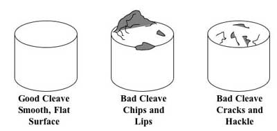
As fibre deployment has become mainstream, splicing has naturally crossed from the outside plant (OSP) world into the enterprise and even the data centre environment. Fusion splicing involves the use of localized heat to melt together or fuse the ends of two optical fibres. The preparation process involves removing the protective coating from each fibre, precise cleaving, and inspection of the fibre end-faces. Fusion splicing has been around for several decades, and it’s a trusted method for permanently fusing together the ends of two optical fibres to realize a specific length or to repair a broken fibre link. However, due to the high costs of fusion splicers, it has not been actively used by many people. But these years some improvements in optical technology have been changing this status. Besides, the continued demand for increased bandwidth also spread the application of fusion splicing.

New Price of Fusion Splicers
Fusion splicers costs have been one of the biggest obstacles to a broad adoption of fusion splicing. In recent years, significant decreases in splicer prices has accelerated the popularity of fusion splicing. Today’s fusion splicers range in cost from $7,000 to $40,000. The highest-priced units are designed for specialty optical fibres, such as polarization-maintaining fibres used in the production of high-end non-electrical sensors. The lower-end fusion splicers, in the $7,000 to $10,000 range, are primarily single-fibre fixed V-groove type devices. The popular core alignment splicers range between $17,000 and $19,000, well below the $30,000 price of 20 years ago. The prices have dropped dramatically due to more efficient manufacturing, and volume is up because fibre is no longer a voodoo science and more people are working in that arena. Recently, more and more fibre being deployed closer to the customer premise with higher splice-loss budgets, which results in a greater participation of customers who are purchasing lower-end splicers to accomplish their jobs.

More Cost-effective Cable Solutions
The first and primary use of splicing in the telecommunications industry is to link fibres together in underground or aerial outside-plant fibre installations. It used to be very common to do fusion splicing at the building entrance to transition from outdoor-rated to indoor-rated cable, because the NEC (National Electrical Code) specifies that outdoor-rated cable can only come 50 feet into a building due to its flame rating. The advent of plenum-rated indoor/outdoor cable has driven that transition splicing to a minimum. But that’s not to say that fusion splicing in the premise isn’t going on.

Longer distances in the outside plant could mean that sticking with standard outdoor-rated cable and fusion splicing at the building entrance could be the more economical choice. If it’s a short run between building A and B, it makes sense to use newer indoor/outdoor cable and come right into the crossconnect. However, because indoor/outdoor cables are generally more expensive, if it’s a longer run with lower fibre counts between buildings, it could ultimately be cheaper to buy outdoor-rated cable and fusion splice to transition to indoor-rated cable, even with the additional cost of splice materials and housing.

As fibre to the home (FTTH) applications continue to grow around the globe, it is another situation that may call for fusion splicing. If you want to achieve longer distance in a FTTH application, you have to either fusion splice or do an interconnect. However, an interconnect can introduce 0.75dB of loss while the fusion splice is typically less than 0.02dB. Therefore, the easiest way to minimize the amount of loss on a FTTH circuit is to bring the individual fibres from each workstation back to the closet and then splice to a higher-fibre-count cable. This approach also enables centralizing electronics for more efficient port utilisation. In FTTH applications, fusion splicing is now being used to install connectors for customer drop cables using new splice-on connector technology and drop cable fusion splicer.

FTTH drop cable fusion splicer

A Popular Option for Data Centres
A significant increase in the number of applications supported by data centres has resulted in more cables and connections than ever, making available space a foremost concern. As a result, higher-density solutions like MTP/MPO connectors and multi-fibre cables that take up less pathway space than running individual duplex cables become more popular.

Since few manufacturers offer field-installable MTP/MPO connectors, many data centre managers are selecting either multi-fibre trunk cables with MTP/MPOs factory-terminated on each end, or fusion splicing to pre-terminated MTP/MPO or multi-fibre LC pigtails. When you select trunk cables with connectors on each end, data centre managers often specify lengths a little bit longer because they can’t always predict exact distances between equipment and they don’t want to be short. However, they then have to deal with excess slack. When there are thousands of connections, that slack can create a lot of congestion and limit proper air flow and cooling. One alternative is to purchase a multi-fibre pigtail and then splice to a multi-fibre cable.

Inside the data centre and in the enterprise LAN, 12-fibre MPO connectors provide a convenient method to support higher 40G and 100G bandwidth. Instead of fusing one fibre at a time, another type of fusion splicing which is called ribbon/mass fusion splicing is used. Ribbon/mass fusion splicing can fuse up to all 12 fibres in one ribbon at once, which offers the opportunity to significantly reduce termination labor by up to 75% with only a modest increase in tooling cost. Many of today’s cables with high fibre count involve subunits of 12 fibres each that can be quickly ribbonized. Splicing those fibres individually is very time consuming, however, ribbon/mass fusion splicers splice entire ribbons simultaneously. Ribbon/mass fusion splicer technology has been around for decades and now is available in handheld models.

Ribbon/Mass Fusion Splicer

Conclusion
Fusion splicing provides permanent low-loss connections that are performed quickly and easily, which are definite advantages over competing technologies. In addition, current fusion splicers are designed to provide enhanced features and high-quality performance, and be very affordable at the same time. FS provides various types and uses of fusion splicers with high quality and low price. For more information, please feel free to contact us at sales@fs.com.

Original article source:
http://www.cables-solutions.com/the-era-of-fusion-splicing-is-coming.html

OTDR Selection Guide

As the use of fibre in premise networks continues to grow, so do the requirements for testing and certifying it. An optical time-domain reflectometer (OTDR) is an electronic-optical instrument used to characterize optical fibres. It locates defects and faults, and determines the amount of signal loss at any point in an optical fibre by using the effects of Rayleigh scattering and Fresnel reflection. By sending a pulse of light into a fibre and measuring the travel time (“time domain”) and strength of its reflections (“reflectometer”) from points inside the fibre, it produces a characteristic trace, or profile, of the length vs. returned signal level on a display screen (as shown in the following picture). This article will describe the key specifications that should be considered when choosing an OTDR.

OTDR

When choosing an OTDR, it is important to select the specific OTDR performance and features according to the required specifications listed below.

Dynamic Range

The dynamic range of an OTDR determines how long of a fibre can be measured. The total optical loss that an OTDR can analyze is mainly determined by the dynamic range. The dynamic range affects the accuracy of the link loss, attenuation and far-end connector losses. Thus, having sufficient dynamic range is really important. The manufacturers specify dynamic range in different way. The higher the dynamic range, the longer the distance an OTDR can analyze.

Dead Zones

Dead zone refers to the space on a fibre trace following a Fresnel reflection in which the high return level of the reflection covers up the lower level of backscatter. To specify an OTDR’s performance, it is important to analyze the dead zone and ensure the whole link is measured. Dead zones are characterized as an event dead zone and an attenuation dead zone. Event dead zone refers to the minimum distance required for consecutive reflective events to be “resolved” (for example, to be differentiated from each other). Attenuation dead zone refers to the minimum distance required, after a reflective event, for the OTDR to measure a reflective or non-reflective event loss.

Resolution

There are two resolution specifications: loss (level), and spatial (distance). Loss resolution is the ability of the sensor to distinguish between levels of power it receives. When the laser pulse gets farther out in the fibre, the corresponding backscatter signal gets weaker and the difference between backscatter levels from two adjacent measurement points becomes larger. Spatial resolution is how close the individual data points that make up a trace are spaced in time (and corresponding distance). The OTDR controller samples the sensor at regular time intervals to get the data points. If it takes readings from the sensor very frequently, then the data points will be spaced close together and the OTDR can detect events in the fibre that are closely spaced.

Pass/Fail Thresholds

This is an important feature because a great deal of time can be saved in the analysis of OTDR traces if the user is able to set pass/fail thresholds for parameters of interest (such as splice loss or connector reflection). These thresholds highlight parameters that have exceeded a warning or fail limit set by the user and, when used in conjunction with reporting software, it can rapidly provide re-work sheets for installation/commissioning engineers.

Post-Processing and Reporting

Report generation could be another major time saver. For example, some OTDRs with specialized post-processing software allow fast and easy report generation, which might reduce the post-processing time up to 90 percent. These reports also include bidirectional analyses of OTDR traces and summary reports for high-fibre-count cables.

Your Applications and Users

Some OTDRs are designed to test long distance optical fibres and some others to test short distance optical fibres. For example, if you are to test premises fiber networks where short distance optical fibres are installed, OTDRs designed for testing long distance optical fibres are not suitable. Besides, knowing your users and the time it will cost is also necessary. Because some types of OTDRs are easy to use and some others are complicated to set up.

When selecting an OTDR, you’re supposed to take all the above factors into consideration. Fiberstore supplies a wide range of OTDRs available with various fibre types and wavelengths (including single-mode fibre, multi-mode fibre, 1310nm, 1550 nm, 1625 nm, etc). They also supply OTDRs of famous brands, such as JDSU MTS series, EXFO FTB series, YOKOGAWA AQ series and so on. OEM portable and handheld OTDRs are available as well.

Fibre Optic Cleaving

To get good fibre optic splices or terminations, especially when using the pre-polished connectors with internal splices, it is essential to cleave the fibre clearly. The term “cleaving” may be somewhat confusing. This article will give you a thorough introduction of it.

Description of Fibre Optic Cleaving

Cleaving is a process of controlled breaking of a bare fibre, which intends to create a perfectly flat endface, perpendicular to the longitudinal axis of the fibre. It begins with making a tiny scratch on the side of the fibre by using a sharp diamond, carbide or ceramic blade, before or while some defined tension or bending is applied to the fibre. Then the fibre breaks and starts at the mentioned scratch point and the scratch propagates rapidly over the full fibre cross-section, leaving a very clean surface on the obtained two fibre ends.

Note: Cleaving is not cutting just breaking in the bulk of the process. And before cleaving, a fibre coating needs to be stripped off with a coating stripper tool, or dissolved with a suitable solvent.

cleave-examples

Importance of Fibre Optic Cleaving

Cleaving is one of the important steps in the preparation for a fibre splice operation. The better results fibre cleaving has, the less splicing loss is. Otherwise, problematic cases occur. For instance, if the fibre ends are not precisely cleaved, the ends will not be mated properly. If the cleaved ends are at an angle, there will be a gap between the fibres that will cause loss in a mechanical splice or uneven fusion splicing. If there is a protrusion, or lip, on one of the fibres, the two fibres will not butt up against each other. If there are surface defects, called hackle or mist, the ends will reflect or diffuse light, causing loss.

Fibre Optic Cleaving Tools

There are two tools used for fibre optic cleaving: cleaver and pen-shaped scribe. Those two tools will be depicted in the following context to make you have a further understanding of cleaving.

A cleaver is a tool that holds the fibre under low tension, scores the surface at the proper location, then applies greater tension until the fibre breaks. As a good cleaver is automatic and produces consistent results, the user need only clamp the fibre into the cleaver and operate its controls.

A pen-shaped scribe is typically used to remove excess fibre from the end of a connector before polishing. It looks like a ballpoint pen, but has a small wedge tip made of diamond or other hard material and applied to scratch the fibre manually. It is used with the “scratch and pull” technique. First the fibre is scribed perpendicular to its length. Then the fibre is pulled to be broken at the scribe. As conducted manually, it requires experienced operators to produce good cleaves.

ct-30 detail

For more information, please visit FS.COM or contact us over sales@fs.com.

Knowledge of Punch Down Tool

Introduction of Punch Down Tool

Punch down tool, also called punch down tool or krone tool (named after the KRONE LSA-PLUS connector), is a small hand tool used by telecom and data network technicians to install wiring for telephone, computer and various audio network, designing for inserting wire into insulation-displacement connectors on punch down blocks, patch panels, keystone modules, and surface mount boxes (also known as biscuit jacks). Its name is derived from the method by which the tool pushes a solid copper wire between metal blades on the connection block and cuts off the excess by punching the tool, driving the tool blade through the wire.

Applications of Punch Down Tool

Punch down tool is commonly used for termination works in the coppper network builted by twisted-pair cables like the Cat5, Cat5e, Cat6 and some newer standard Ethernet cables. With cables terminated with keystone jacks, cross-connect blocks or patch panels, networks run smoothly, enhancing working efficiency and reducing losses. For instance, it is widely used by IT staff to ensure successful connections between computers and data centre, maintaining a high level of transmission.

punch down tool

Tips When Using Punch Down Tool

Procedures

  • Hold the wire in your hand and lace it through the correct slots on the connection block. Repeat with other wires that need to be inserted in the connection block.
  • Hold the punch down tool with the blade facing down. Align the blades with the wires on the connection block.
  • Punch down the wire by holding the wire and pushing the tool firmly into the block. This should connect the wire to the terminal and cut off any excess wire at the same time.
  • Test the connection you just created. Pull on the wires to make sure they are attached properly.

Note: It is essential that the tool blade should not cut throughout the wire insulation to make contact, but rather the sharp edges of the slot in the contact post itself slice through the insulation. In addition, punch down tool is also used to cut off excessive wire in the same operation.

Warnings

  • Always wear safety glasses when using a punch down tool.
  • Models with interchangeable blades will extend the life of your tool.
  • Use the pressure adjustment screw or knob to set the tool to a comfortable level for your use.
  • Never use a punch down tool to tighten flat head screws because this can break the cutting blade.
  • Although the tool is usually made of plastic, there still is a shock hazard when working with electrical circuits.

FS.COM offers impact punch down tool with competitive price such as the 110 punch down tool, Krone punch down tool. Please visit our website or contact us over sales@fs.com

Introduction of Phone Line Tester

Description of Phone Line Tester

Phone line tester is a pockets-sized device used for basic troubleshooting of analog phone systems as well as the line polarity. It monitors phone lines for digital-tone quality and signal power, tests of correct jack polarity (detects reversed tip and ring), and indicates call addressing for correct telephone extensions.

What is Phone Line Tester Used For?

Phone line tester is mainly applied to check the operating parameters of the telephone company’s wiring at the modular connector which includes the open circuit or “on-hook” line voltage, the ringer voltage, and the polarity of the line. The phone line’s voltage conditions are indicated by a meter and the polarity of the line connections is indicated by an LED. The wires in the phone cables are colour-coded, with the green wire being the positive side, and the wire being the negative side. When there is no load on the line, that is, when all phones in your home or office are oil hook, the measured voltage at your phone’s modular connector should be greater than 40-volts DC, give or take a smidgen. And normally, polarity is normally not a problem for most standard phones will work regardless of the polarity of the DC voltage on the telephone line. However, reversed line polarity can interfere with certain kinds of switching equipment, in particular, some of the low-cost conference and multi-use switchers, so we’ve provided for that test.

How does a Phone Line Tester work?

The phone line tester shown in the following picture is connected to the phone line through modular connector P1. The tester only uses two of its four connectors-the red and the green. If it is correct-that is, if the green wire is the positive side-and the red wire is the negative side, nothing will happen. If the situation is reversed. The LED will light. With switch SI Set for LINE/RING. Both S1-a and S1-b are open and the meter indicates the condition of the line-voltage. Any line voltage reading in the LINE OK range (more on the meter in a moment) indicates a line voltage higher than 40-volts DC. If the telephone is caused to ring, either by using a ring back number or by dialing from another phone, the meter will indicate RING OK, and the LED will pulse (indicating AC), if the ringing voltage/current is correct. The actual position of the meter’s pointer depends on how ringers are connected across the line. (Three or more of the old-fashioned ringers can excessively load the ringing voltage if the local telephone company has not corrected for your ringer load.) When S1 is closed the voltage range of the meter is changed and a nominal load resistance of 230 ohms (R5 and R6) is connected across the line to emulate the off hook load of the telephone. If the meter indicates LOOP OK, you can be certain that you have sufficient loop voltage for satisfactory telephone operation. If you place another load on the line, perhaps by taking an extension telephone off hook, the meter reading will almost invariably drop below the LOOP OK range. That is perfectly normal; the line is operating properly when a single loop load results in a LOOP OK meter reading. That is how to test telephones for proper connection. If lifting the handset causes the meter reading to drop, you can at least be certain that the telephone’s hook switch is working and that the repeat coil is connected to the line.

line tester

Features of Phone Line Tester

  • Receiving and reproducing telephone system dial tone to determine the quality of the tone
  • Equipped for jack and cross-connect systems access
  • Receiving tracing signals for identifying specific conductors in a cable run (TRACE function requires a separate tone generator)
  • Volume control to adjust test tones
  • Durable, moisture-resistant case and speaker for long-life durability

Introduction of Network Tester

Network tester is a device used for logging and monitoring your internet connection, network or maintain uptime stability. It is a dispensable tool for managers to troubleshoot network problems and maintain the network actively, such as troubleshooting your video, audio, data, and voice network cables during installation or testing to make sure your signal is good.

Network testers can be divided into different types depending on two standards: network transmission and function media. By network transmission media they can be divided into two kinds: wireless network testers and line network testers. And by its function they can be classified into three types: cable testers, multifunction network testers and network performance testers. Of those various types of testers, the most common used network tester for network administrators and installers is cable tester which is designed to test the strength and connectivity of a particular type of cable or other wired assemblies. It can test whether cables or wires are set up and connected appropriately and if the communication strength between the source and destination is strong enough to serve its intended purpose.

Network Cable TesterNetwork testers are mainly applied in two aspects, one is testing and maintaining the equality and data of network construction equipment which is widely used in comprehensive wiring system. Another is troubleshooting problems of network maintenance equipment which attached importance to products’ multiple functions and applications. And network testers are utilized in a wide range of fields including LAN administration, comprehensive wiring system, data centres, bandwidth operation, and network computer lab.

There are few tips for you when using network tester.

  • Some important network characteristics including utilisation levels, number of users, and application utilisation must be noticed and each network should be evaluated individually.
  • Comprehensive network testing will enable a network manager to maintain the network with high efficiency. So a properly implemented network testing schedule is of high importance which provides a valuable insight to trends or changes in the network’s daily operation. This insight may allow the network manager to predict network operation under a given load, or anticipate problems created by new services.

Fiberstore offers various network cable testers, from basic to complicated,with high quality at good prices. FiberStore supplies so many kinds of LAN Network Cable Tester, which are a kind of convenient and comprehensive tool for network professionals.