Category Archives: Fiber Cables

Confused by Fiber Cable Types?

A friend has told me that she had some trouble in selecting the fiber cable recently. Maybe there are many people like her that are confused by fiber cable types. If you happen to be the one, you can find the answer in this article.

Different Fiber Cable Types Based on Fiber Cores

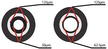
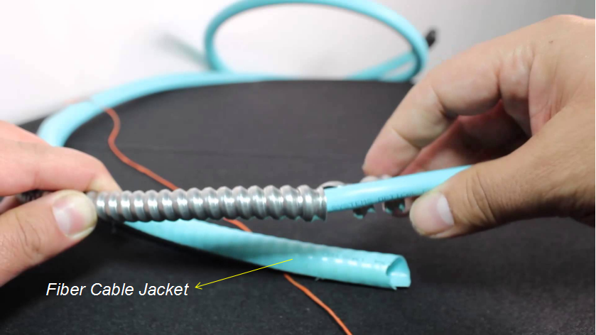
OM1 cable is typically wrapped by an orange jacket and has a core size of 62.5 micrometers (µm). It can support 10 Gigabit Ethernet at lengths up 33 meters. It is most commonly used for 100 Megabit Ethernet applications.

OM2 also has a suggested jacket color of orange. Its core size is 50µm instead of 62.5µm. It supports 10 Gigabit Ethernet at lengths up to 82 meters but is more commonly used for 1 Gigabit Ethernet applications.

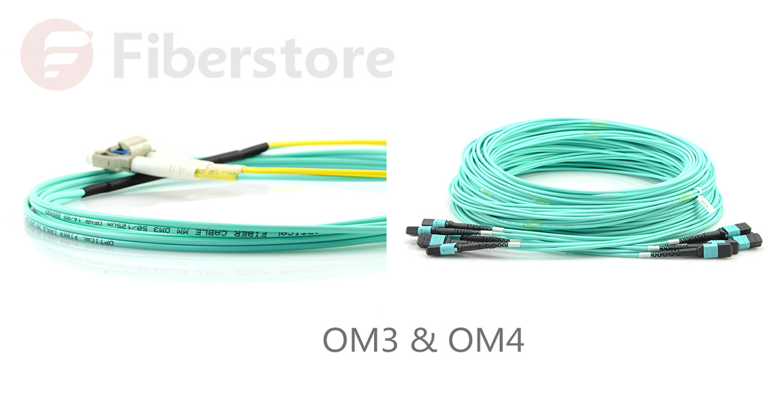
OM3 has a suggested jacket color of aqua. It has a core size of 50µm, same with OM2, but the cable is optimized for laser based equipment that requires fewer modes of light. As a consequence of this optimization, it is capable of running 10 Gigabit Ethernet at lengths up to 300 meters. Since its inception, production techniques have improved the overall capabilities of OM3 to enable its use with 40 Gigabit and 100 Gigabit Ethernet up to 100 meters. 10 Gigabit Ethernet is its most common use.

OM4 also has a suggested jacket color of aqua. It is a further improvement to OM3. It too uses a 50µm core but it supports 10 Gigabit Ethernet at lengths up 550 meters and it supports 100 Gigabit Ethernet at lengths up to 150 meters.

All these are multimode fiber. As it is typically cost effective for inside buildings or corporate campuses, I strongly recommend it regarding the fact that some of you, like my friend, want it for private use and are on a limited budget. If you want to know more about these different types of fiber cables, you can read Multimode Fiber Types: OM1 vs OM2 vs OM3 vs OM4 vs OM5.

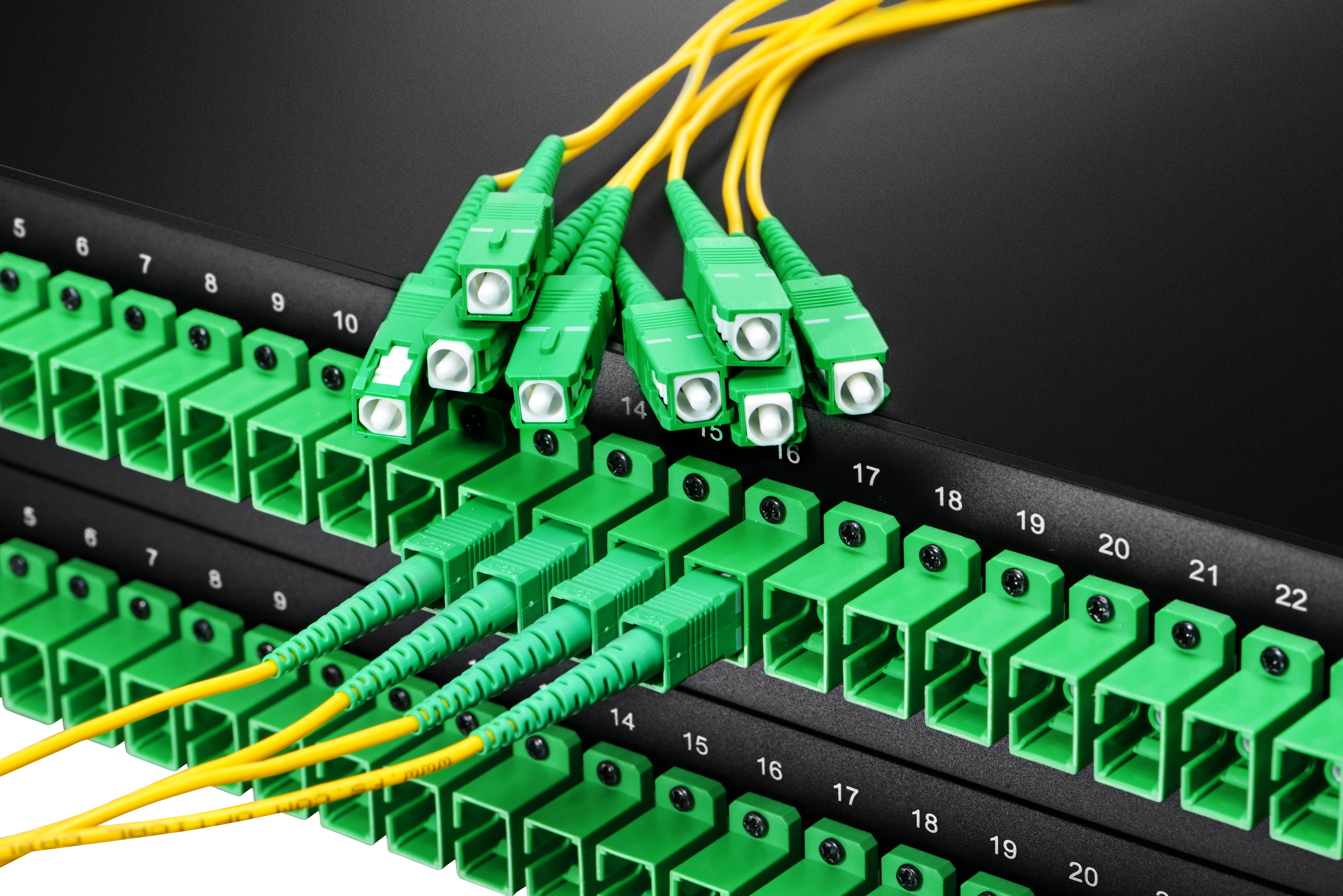
Different Fiber Cable Types Based on Connectors

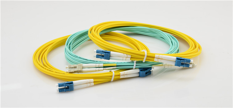
Fiber patch cables can be categorized into many types according to cable connectors. If the connectors attached to the two ends of the cable are the same one, this cable named same-connector type fiber patch cord. Otherwise, it is hybrid fiber patch cord which has different connectors on each end, like fiber patch cord LC to SC. Next, I will take the examples of LC-LC fiber patch cable, SC-SC fiber patch cable and LC-SC fiber patch cable.

LC-LC Fiber Patch Cable

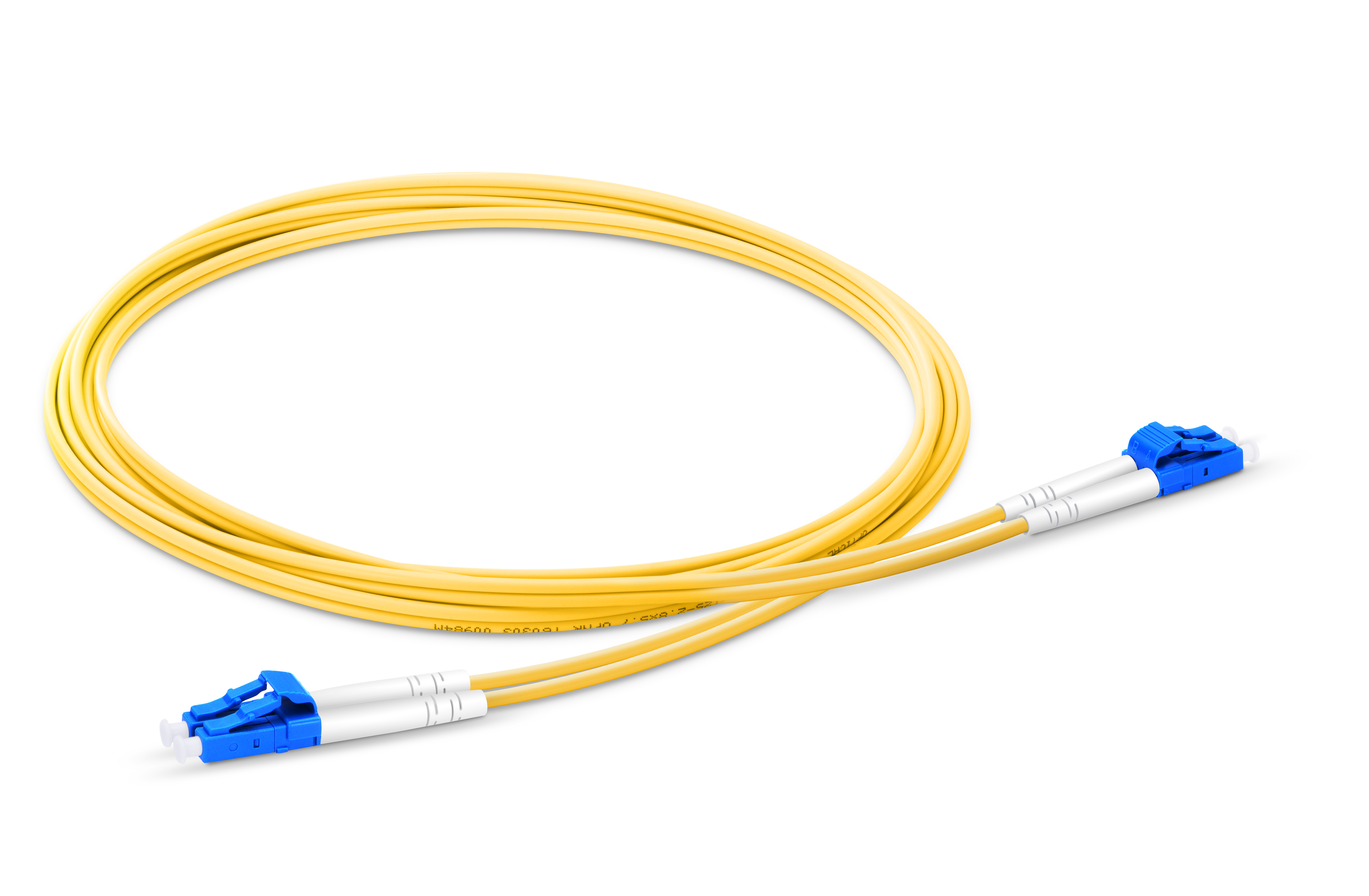
LC to LC fiber optic cables, as one kind of fiber optic patch cables, possesses lots of advantages such as low insertion loss and back reflection loss, good durability, high temperature stability, good interchangeability and duplication. Thus they are widely used in Gigabit Ethernet and fiber channel, multimedia, telecommunication, and high speed data transmission throughout the network, etc.

fiber cable types-LC LC

SC-SC Fiber Patch Cable

Two SC fiber connectors terminated at the ends of the cable offer excellent packing density, and its push-pull design reduces the chance of fiber end face contact damage during connection. However, these big SC connectors may add to the size of the whole patch cable.

SC SC

LC-SC Fiber Patch Cable

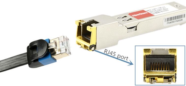
LC-SC fiber cables are available in single mode and multimode types, in simplex and duplex versions. LC connector has a low insertion loss, and a relatively small size. And LC is suitable for densely populated racks/panels. SC is ideally suited for datacoms and telecoms applications. This cable boasts the advantages of LC and SC connectors.

Conclusion

Apart from what is mentioned above, there are many fiber cable types I haven’t put forward due to the limited time. If you have different purposes and different requirements, you can turn to FS.COM. Experts will be there answering your puzzles and offering you the best service.

Five Basics About Fiber Optic Cable

A fibre optic cable is a network cable that contains strands of glass fibres inside an insulated casing. They’re designed for high performance data networking and telecommunications. Fibre optic cable carry communication signals using pulses of light, faster than copper cabling which uses electricity. They are becoming the most significant communication media in data centre. Then how much do you know about them? This post serves as a guide for beginners.

Fibre Components

The three basic elements of a fibre optic cable are the core, cladding and coating. Core is the light transmission area of the fibre, either glass or plastic. The larger the core, the more light that will be transmitted into the fibre. The function of the cladding is to provide a lower refractive index at the core interface, causing reflection within the core. Therefore the light waves can be transmitted through the fibre. Coatings are usually multi-layers of plastics applied to preserve fibre strength, absorb shock and provide extra fibre protection.

Fiber Components

Fibre Type

Generally, there are two basic types of fibre optic cables: single mode fibre (SMF) and multimode fibre (MMF). Furthermore, multimode fibre cores may be either step index or graded index.

Single mode and multi-mode fiber-optic cables

Single mode optical fibre is a single strand of glass fibre with a diametre of 8.3 to 10 microns that has one mode of transmission. The index of refraction between the core and the cladding changes less than it does for multimode fibres. Light thus travels parallel to the axis, creating little pulse dispersion. It’s often used for long-distance signal transmission.

Step index multimode fibre has a large core, up to 100 microns in diametre. As a result, some of the light rays that make up the digital pulse may travel a direct route, whereas others zigzag as they bounce off the cladding. These alternative pathways cause the different groupings of light rays to arrive separately at a receiving point. Consequently, this type of fibre is best suited for transmission over short distances.

Graded index fibres are commercially available with core diametres of 50, 62.5 and 100 microns. It contains a core in which the refractive index diminishes gradually from the centre axis out toward the cladding. The higher refractive index at the centre makes the light rays moving down the axis advance more slowly than those near the cladding.

Fibre Size

Single mode fibres usually has a 9 micron core and a 125 micron cladding (9/125µm). Multimode fibres originally came in several sizes, optimised for various networks and sources, but the data industry standardized on 62.5 core fibre in the mid-80s (62.5/125 fibre has a 62.5 micron core and a 125 micron cladding. It’s now called OM1). Recently, as gigabit and 10 gigabit networks have become widely used, an old fibre design has been upgraded. 50/125 fibre was used from the late 70s with lasers for telecom applications. 50/125 fibre (OM2) offers higher bandwidth with the laser sources used in the gigabit LANs and can allow gigabit links to go longer distances. Laser-optimised 50/125 fibre (OM3 or OM4) today is considered by most to be the best choice for multimode applications.

Basic Cable Design

The two basic cable designs are loose-tube cable, used in the majority of outside plant installations, and tight-buffered cable, primarily used inside buildings.

loose-tube-or-tight-buffered-cable

The modular design of loose-tube cables typically holds up to 12 fibres per buffer tube with a maximum per cable fibre count of more than 200 fibres. Loose-tube cables can be all dielectric or optionally armored. The modular buffer-tube design permits easy drop-off of groups of fibreers at intermediate points, without interfering with other protected buffer tubes being routed to other locations.

Tight-buffered cables can be divided into single fibre tight-buffered cables and multi-fibre tight-buffered cables. single fibre tight-buffered cables are used as pigtails, patch cords and jumpers to terminate loose-tube cables directly into opto-electronic transmitters, receivers and other active and passive components. While multi-fibre tight-buffered cables also are available and are used primarily for alternative routing and handling flexibility and ease within buildings.

Connector Type

While there are many different types of fibre connectors, they share similar design characteristics. Simplex vs. duplex: Simplex means 1 connector per end while duplex means 2 connectors per end. The following picture shows various connector styles as well as characteristics.

fiber cable connectors

Summary

Ultimately, what we’ve discussed is only the tip of the iceberg. If you are eager to know more about the fibre optic cable, either basics, applications or purchasing, please visit www.fs.com for more information.

Tips for Fibre Cable Installation You Should Know

Fibre cable installation is not an easy task for most of us. It’s thought as the job of professional engineers since special training is needed during the complicated process. But it would be better if you know knowledge of fibre cable installation in case that you need to run fibre cable in your home or business. This article is going to offer you some tips for fibre cable installation.

fiber-cable-installation

Before Fibre Cable Installation

Before starting fibre cable installation, please make sure there is fibre optic service in your area. If it’s available, find the nearest distribution box. What you need to do is to run fibre cable from the box to your house.

A considerate plan is the first step of successful fibre cable installation. Carefully design the cabling route. It would be better if you mark where the cable goes, into the walls, or underground, or through conduit… Point out all the termination points and splice points. At the same time, write down any potential problems you may come across during the installation. A good plan is also beneficial to avoid fibre cable waste.

Once finish the plan, you’re going to buy fibre optic cable for your applications. Except fibreoptic cable, you need tools for cable management & installation, fibre splicing and fibre testing. So make a shopping list for your fibre cable installation. Then select a reliable fibre cable supplier who can meet the requirements of both high quality and low cost.

During Fibre Cable Installation
What You Should Do

Leave spare cable length—Each fibre cable for installation should be a few inches longer than the plan says. Because you can’t make sure everything goes as you wish. So you should leave plenty of spare fibre cables when beginning cable installation work.

Avoid electrical interference—Though fibre cable is not as vulnerable to electrical noise as copper cables, some devices, such as the boxes for fluorescent lights, may cause interference. So keep your fibre cable three or more feet from those devices.

Avoid end face contamination—The tip of fibre optic connector can be easily contaminated or damaged. So leave protective caps on until you are ready to plug into the equipment. Don’t forget to inspecting the end face before plugging in. If there is any contaminate, clean it.

Fibre network testing—Test each section of your fibre optic network. That’s easy to discover the problem and troubleshoot it. Don’t do this work until you finish the entire cable installation. In that situation, it’s hard to find out the trouble if the network fails.

What You Should Not Do

Don’t bend fibre cables. Fibre optic cables perform the best when it is running straight. But during installation in reality, sometimes bending can’t be avoided. Cables from different vendors may have different standards of bend radius. Or you can buy bend insensitive fibre cable for better performance.

Don’t pull too hard on the cable. Properly pull the fibre cable to avoid bending or snagging through the conduit or underground. However, don’t pull it too hard especially when the fibre cable is too short. Otherwise, it would ruin the cable or fibre optic connector.

Don’t mix and match different core sizes. Fibre optic cables are typically colour coded. From the outside cable jacket, you can get information about fibre core sizes. To know more about fibre cable jacket, you can visit my last blog What Can We Get From Fibre Cable Jacket?

Don’t pinch the fibre cable. Pinch the fibre cable can squeeze the fibre and affect link performance. When use zip-ties, pay attention to this point.

Conclusion

Once you finish fibre cable installation, you can enjoy fibre optic network. See, fibre cable installation is not as tough as you think. Follow these tips mentioned above when you run cables for your house, you can keep away from most bothering issues.

What Can We Get From Fibre Cable Jacket?

Fibre optic cable is applied as the most advanced communication medium by more and more users. Compared with copper cable, it can support more and better optical signal transmission of voice, data, video, etc. and offer many other advantages. When purchasing fibre optic cables, you must see the cable jacket at first. So what information does the outside jacket tell? What type of cable jacket should you select? Come with me to find the secrets of fibre cable jacket.

Fibre Cable Jacket Introduction

Fibre optic cable is constructed very complicated from the inside core, cladding, coating, strengthen fibres to the outside cable jacket. The core made of plastic or glass is the physical medium for optical signal transmission. As bare fibre can be easily broken, cable outer jacket is needed for fibre protection. The cable jacket is the first line of moisture, mechanical, flame and chemical defense for a cable. Without the jacket, fibre optic cables are very likely to be damaged during and after installation.

fiber-cable-jacket

Fibre Cable Jacket Characteristics

In most situations, robust cable jacket is better because the environment above or underground may be harsh. For better applications, you’d better take cable jacket seriously. Cable jacket is not as easy as you think. There are many characteristics you need to consider. Except the flexibility, it should withstand very low and high temperature. Whether the cable jacket has the good features of chemical and flame resistance. All these characteristics depend on cable jacket materials.

Fibre Cable Jacket Materials

Cable jacket is made of various types of materials. As mentioned above, the cable jacket should stand the test of different environmental conditions, including the harsh temperature, the sun & the rain, chemicals, abrasion, and so on. The following shows several common cable jacket materials for your reference.

PE (Polyethylene)—PE is the standard jacket material for outdoor fibre optic cables. It has excellent properties of moisture and weather resistance. It also has the good electrical properties over a wide temperature range. Besides, it’s abrasion resistant.

PVC (Polyvinyl Chloride )—PVC is flexible and fire-retardant. It can be used as the jacket materials for both indoor and outdoor cables. PVC is more expensive than PE.

LSZH (Low Smoke Zero Halogen)—LSZH jacket is free of halogenated materials which can be transformed into toxic and corrosive matte during combustion. LSZH materials are used to make a special cable called LSZH cable. LSZH cables produce little smoke and no toxic halogen compounds when these cables catch fire. Based on the benefits, LSZH cable is a good choice for inner installations.

Fibre Cable Jacket Colour

Fibre cable jacket colour depends on the fibre cable type. Fibre cable includes single-mode and multimode types. For single-mode fibre cable (Blog about single-mode fibre cable please read my blog What Are OM1, OM2, OM3 and OM4?), the jacket colour is typically yellow. While for multimode cable ( more details on multimode fibre cable ), the jacket colour can be orange (OM1&OM2 cable), aqua (OM3 cable) and purple (OM4 cable). For outside plant cables, the jacket colour is black.

How to Choose Fibre Cables?

To choose a fibre optic cable depends on your own applications. I’ll talk about this from two sides of jacket colour and jacket material. The cable jacket colour is not just for good looking. Different colour means different fibre mode. Which one suits you the most, the yellow or orange fibre cable? You should know well about the colour codes before buying your fibre cables. What’s more, you should also consider the installation requirements and environmental or long-term requirements. Where will be your fibre cables installed, inside or outside the building? Will your cables be exposed to hash environment very long? This can help you decide which jacket material is the best.

Summary

As a popular data transmission medium, fibre cable plays an important role in communication field. To some degree, the success of fibre connectivity lies in a right fibre cable. How to buy suitable fibre optic cables? This article describes the method from cable jacket. When selecting fibre cable, many other factors still need to be considered. Hope you can get your own fibre cable.

Advice on Patch Cable Selection for Optical Transceiver

Fibre optic network connection can’t be achieved without optical transceiver and patch cable. Optical transceiver varies from transmission media, interface, transmission distance, data rate, and brand, for example, SFP for 1000Mbps, SFP+ for 10G, QSFP+ for 40G, CFP and QSFP28 for 100G. It’s not difficult to identify these optical transceivers. But when you connect the optical transceiver to the patch cable, many details need to be noticed. This article will give you advice on how to choose the suitable patch cable for your optical transceiver.

Transmission Media—Copper & Fibre

According to transmission media of fibre optic and copper, transceivers can be divided into two kinds, copper based transceivers and fibre optic based transceivers. MSA has defined several copper based transceiver like: 100BASE-T, 1000BASE-T and 10GBASE-T. Copper transceivers are available in GBIC, SFP and SFP+ form factors, which usually has an RJ45 interface. So Cat5/6/7 cables are typically used to connect with the transceivers. Maybe Cat8 will be researched and developed to support higher data rate up to 40G sooner or later.

optical-transceiver-rj45-interface

As to fibre optic transceivers, things are more complex. For that fibre optic transceivers require different fibre patch cords which have more types. Fibre patch cables cover single-mode and multimode. Single-mode patch cable can be classified into OS1 and OS2. While multimode cables can be divided into OM1, OM2, OM3, OM4 cable. Different cables are used in different applications. Single-mode cable can support long distance transmission and multimode cable for short distance link. If the transmission distance is shorter than 500 metres, multimode patch cable is suggested. For long distance transmission, single-mode transmission is suggested. You patch-cableshould also consider that the transmission data rate can also affect the transmission distance. Let’s look at the following point.

Supported Distance and Data Rate

MSA has defined a variety of transceivers that can support different transmission distances and data rates. When you buy a fibre optic transceiver, you will find the data rate, wavelength, distance, etc. on its labeling. The following table show the basic information of most often used transceivers and supported cable type.

Description Wavelengh Data Rate Cable Type Distance
SX 850nm 1G MM 500 m
LX 1310nm 1G SM 8 km
EX 1310nm 1G SM 40 km
ZX 1550nm 1G SM 70 km
SR 850nm 10G MM 300 m
LR 1310nm 10G SM 10 km
ER 1550nm 10G SM 40 km
ZR 1550nm 10G SM 80 km
SR4 850nm 40G MM 100 m
SR10 850nm 100G MM 100 m
LR4 1310nm 40G SM 10 km

As mentioned before, single-mode patch cable is better for long distance transmission and multimode patch cable for short distance transmission. Actually single-mode patch cords can be used for different data rates in both long and short distances. But single-mode fibre optic cable will cost more. To achieve reliable performance in short distances with cost effective solutions, you should know the performance of multimode fibre optic cables. The following chart provides the detailed transmission distances and data rates information for different multimode fibre optic cables over wavelength of 850 nm for your reference.

Fibre Type 1G 10G 40/100G
OM1 300 m 36 m N/A
OM2 500 m 86 m N/A
OM3 1 km 300 m 100 m
OM4 1 km 550 m 150 m
Transceiver Interfaces

The selection of patch cable for transceiver should also consider the interfaces through which patch cords is connected to the transceiver. In addition, transceiver usually used one port for transmitting and one port for receiving. Generally, fibre optic transceivers usually employs duplex SC or LC interfaces. However, for BiDi transceivers only one port is used for both transmitting and receiving. Thus, simplex patch cord is used with BiDi transceiver.

Some 40G/100GBASE QSFP+ transceivers used MTP/MPO interfaces, which should be connected to the network with multi-fibre patch cords attached with MTP/MPO connectors. If these ports are used for 40G to 10G or 100G to 10G connection, then fanout patch cable should be used. For example, a MTP to 8 LC fanout cable can splitter 40G data rate to four 10G data rate.

Summary

Next time when you select patch cords for your fibre optic transceivers, you can consider these factors like transmission media, transmission data rate and distance, transceiver interfaces. FS.COM offers a wide range of fibre optic transceivers and patch cords. Custom service is also available. Any problem, please contact us via sales@fs.com.

What Should We Know Before Deploying 10 Gigabit Ethernet Cable?

Since the need for high data speed increases and the price of optical equipment becomes more affordable, many enterprises start to deploy 10 Gigabit Ethernet cables in their cooperate backbone, data centres to support high-bandwidth applications. But what should we know before deploying 10 Gigabit Ethernet cables?

Fibre Choices for Deploying 10 Gigabit Ethernet Cable

Three factors should be considered for fibre cable deployment: fibre cable type, 10 Gigabit Ethernet physical interface and fibre optical transceiver module. The following tables show the standard fibre cables, physical interfaces, and transceiver module applicable to 10 Gigabit Ethernet.

Fibre Cables Multimode OM1 fibre (62.5/125 μm)
OM2 fibre (50/125 μm)
OM3 fibre (50/125 μm)
Single mode 9/125 μm fibre
Physical Interfaces 10GBase-LRM Max distance 220m
10GBase-S Max distance 300m
10GBase-L Max distance 10km
10GBase-E Max distance 40km
10GBase-Z Max distance 80km
Transceiver modules XENPACK Large form factor
X2 Smaller than XENPACK
XFP Smaller than X2
SFP+ Smallest form factor

Note: the 10 Gigabit Ethernet physical interface type should be the same on both ends of the fibre link. For example, it is OK to deploy a fibre link with one XFP-10G-MM-SR optics on the left, and one SFP-10G-SR optics on the right. However, one SFP-10G-SR optics and one SFP-10G-LRM optics can’t connect together because of different physical types.

Copper Choice for Deploying 10 Gigabit Ethernet Cable

As switching standards copper cabling standards develop, copper cabling for 10GbE is more widely used. There are three different copper technologies for deploying 10 Gigabit Ethernet cables. Each one has different performances and prices.

First, 10GBase-CX4 is the first 10 Gigabit Ethernet copper cable standard. It’s relatively economical and allows for very low latency. But the form factor is too large for high density port counts in aggregation switches.

Second, Small Form-factor Plus (SFP+) is the latest standard for optical transceivers. 10 Gb SFP+Cu Direct attach cables (DAC) directly connect into an SFP+ housing. It’s the best copper solution for servers and storage devices because it has low latency, small form factor and reasonable price.

Third, 10GBase-T is a fully IEEE compliant Ethernet transport technology standard, as defined by IEEE 802.3an-2006. 10GBase-T is to run 10 Gigabit Ethernet over CAT6a and CAT7 copper cabling up to 100 metres. 10GBase-T copper twisted-pair cabling can enable the earlier 10MB, 100MB and 1GB operation. However, 10GBase-T still needs to be improved on its price, power consumption and latency.

Media Copper cable Range (max) Average Latency
CX4 Twinax 15m (49ft) 0.1 μs
SFP+ DAC Twinax SFP+CU 10m (33ft) 0.1 μs
10GBase-T CAT6 RJ45 30m(98ft)—50m (164ft) >1.5 μs
CAT6a RJ45 100m (98ft) >1 μs
CAT7 GG45 100m (98ft) >1 μs
SFP+ Direct Attach Cables

SFP+ DAC cable integrates SFP+ compatible connectors with a copper cable into a low-latency, energy-efficient, and low-cost solution. SFP+ direct attach cables offer the smallest 10 Gigabit form factor and a small cable diametre for higher density and optimised rack space in 10 Gigabit Ethernet (GbE) uplinks and 10 Gigabit Fibre Channel SAN and NAS input/output connections. To use SFP+ direct attach cables can save you a lot compared with fibre optic solutions. And it can still provide lower latency and save up to 50% power consumption per port than other copper twisted-pair cabling systems.

sfp+ dac

SFP+ direct attach cables can also provide enhanced scalability and flexibility. The cables connect several servers or storage devices together in a single rack. Thus, it reduces the use of intermediate patch panels. And it’s easy to move racks or deploy one rack at a time since the cabling outside of the rack is limited to the main switch connection.

FS offers comprehensive solutions for 10 Gigabit Ethernet cabling, including fibre cables, copper cables, and SFP+ direct attach cables and each one has various subcategories. Before deploying 10 Gigabit Ethernet cables, you need to consider factors of the performance, cost, power consumption and latency and choose the most suitable cabling solution.

Related Article: Cisco SFP-10G-SR: All You Need to Know

Which One Will You Choose for Your 40/100G Network, OM3 or OM4?

40G has been widely used in data centres. 100G will also come soon. To meet these high bandwidths, related fibre cables are needed. OM3 and OM4 can be used to transmit parallel optical signal. But what is their difference? Which one will you choose for your network?

Both OM3 and OM4 are laser optimized fibre. Their cores size is 50/125. Connectors are the same and both operate 850nm VCSELS (Vertical-Cavity Surface-Emitting Lasers) transceivers. So the difference lies in the construction of the fibre cable, which means OM4 cable has better attenuation and can operate at higher bandwidth than OM3.

OM3-and-OM4

Attenuation is the reduction in power of the light signal as it is transmitted (dB). Attenuation is caused by losses in light through the passive components, such as cables, cable splices, and connectors. As the connectors are the same, so the difference in OM3 and OM4 performance is in the loss (dB) in the cable. The maximum attenuation of OM3 allowed at 850 nm by the standards is less than 3.5 dB/km, and less than3.0 dB/km for OM4.

Another factor influencing the cable function is dispersion. Dispersion is the spreading of the signal in time due to the different paths the light can take down the fibre. It has two types: chromatic and modal. In multimode fibre transmission, chromatic dispersion is negligible and the modal dispersion is the limiting factor.

The modal dispersion determines the modal bandwidth that the fibre can operate at and this is the difference between OM3 and OM4. Modal bandwidth represents the capacity of a fibre to transmit a certain amount of information over a certain distance and is expressed in MHz*km. The higher the modal bandwidth the more information can be transmitted. The modal bandwidth of OM3 is 2700 megahertz*km while the mod0al bandwidth of OM4 is 4700 megahertz*km. Thus, OM4 allows the cable links to be longer.

Compared with OM3, OM4 has a lower attenuation and operates at a higher modal bandwidth. That means over OM4 less power is lost during the signal transmission and the signal can be transmitted further or through more connectors (which add to the losses). The following table shows the Ethernet distances at 850 nm supported by OM3 and OM4 respectively.

1Gb 10Gb 40Gb 100Gb
OM3 1000m 300m 100m 100m
OM4 1000m 500m 150m 150m

So why is the standard for 40G only 100m on OM3 and 150m on OM4 compared to 300m and 500m for 10G? There are two reasons. First, when the IEEE 802 standard was created they decided to create a standard based on “relaxed” transceiver specifications so that smaller and lower cost transceivers could be used. Two functions of 10G transceivers (clock recovery and attendant re-timing) are absent in both QSFP+ (40G) and CFP (100G) devices. Second, the standard allows for transceivers with wider spectral width lasers which increase chromatic dispersion (pulse spreading). The quality of transceivers is also a factor.

Which will you choose for your 40/100G network, OM3 or OM4? Except the transmission distance and the cable costs, there are additional factors to consider such as the number of cross connects required and the mix of 40G port to 40G port and 40G port to 10G port. Because 40G signal is transmitted across eight pairs of fibre each with 10G. Similarly, it is important to take into account the likely location of future 100G equipment and the possible 100G to 100G, 100G to 40G and 100G to 10G connectivity requirement.

Hermetic Carbon-coated Optical Fibre

There are many types of polymer coatings used to protect optical fibre from mechanical damage. However, those common polymer-coated fibres are just used for ordinary applications but not for special applications. The special applications including high-stress applications and adverse environments require optical fibres with improved hermeticity, strength and chemical resistance, etc. So what kind of fibres do we need for special applications?

Hermetic optical fibres are thought to be the ideal solution for the special applications. One type of real hermetic coatings for optical fibres is carbon. Carbon coatings on the surface of optical fibre was developed by AT&T Bell Labs. The thickness of the carbon coating on a 125 μm is usually 50 nm. The coating is so thin that fibre surface cannot avoid being damaged even with the most careful handling. So secondary coating is required. However, due to the thin coating, carbon-coated fibres have no additional optical loss, which makes them are a perfect solution in high-speed networks.

Those kind of carbon-coated optical fibres have three main advantages for its hermetic coatings. The hermetic coatings can protect the fibre surface from water vapor, which reduces static fatigue effects and enhance the fibre mechanical reliability. And they can also defend the fibre surface against mechanical and chemical damage at high temperatures. In addition, those hermetic coatings can stop penetration of hydrogen to the fibre core, making optical networks efficient in hydrogen-containing environment. Here is a picture which shows the attenuation of both hermetic and non-hermetic fibres in a typical operating window for DTS systems. Affected by the hydrogen absorption spectrum, they are of distinct reflections. It is obvious that the optical fibre need to be protected from the hydrogen in diffusion to extend the fibre’s lifetime in a down hole environment.

the-attenuation-of-both-hermetric-and-non-hermetric-fibers-in-a typical-operating-window-for-DTS-systems

hermetric-carbon-coated-fibers-for distributed-temperature-sensing
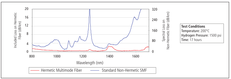
With above advantages, hermetic carbon-coated fibres can be applied for special applications including high-stress applications (tensile stress, bending stress, torsional stress), adverse environment (water, solvents, high operating temperatures, elevated pressures), etc. For instance, hermetic carbon-coated fibres can be deployed down stainless steel tube during oil well completion for distributed temperature sensing. Those fibres, also called optical sensing fibres, are used as distributed sensors to measure temperature, pressure and flowing information of the wells in harsh conditions. The typical down-hole environments usually are at temperatures up to 300℃ and under pressures up to 30,000 psi, which requires hermetic fibres with high reliability. Hermetic carbon-coated fibres are now popular in chemical and oil industry.

FTTH Indoor Cable

FTTH has been widely deployed as the high demand for bandwidth of video, audio and data signals transmission. More and more FTTH networks have been and will be installed in subscribers’ houses due to growing requirements for them and enhancements on their technologies. A variety kind of FTTH cables are accordingly designed including in-duct cables, direct-buried cables, drop cables and indoor cables, etc. FTTH indoor cables are mostly difficult to be installed among those cables for the complex indoor environment. Today, this article will introduce FTTH indoor cables in details.

What Is FTTH Indoor Cable?

FTTH indoor cable is used inside a building or house to connect the FTTH user end equipment. Its fibre count typically is 1, 2 or 4 optical strands commonly combined with two non-metal enhanced FRP/Metal/KFRP which can provide sufficient tensile strength and good resistance to lateral crushing to protect the fibre inside. In addition, its outer sheath is universally consist with LSZH material with good flame-retardance in white or black. Its simple convenient structure makes it perfect for indoor cabling.FRP Strength member FTTH indoor cable

Installation of FTTH Indoor Cable

FTTH indoor cable is usually installed along the walls, behind moldings, around corners or through ceilings. The local environment including building styles, existing ducts, owners’ personal requirements and life security control decides the specific operation like the length and bend amplitude of the indoor cable. And nowadays the cables need to have both mechanical strength and flexible installation capacity for smaller subscribers’ houses as the rapid development of FTTH. The bend-optimised cables are prevailing in FTTH indoor installation for its great bend performance around the sharp edges and corners in smaller houses. The following pictures show the installation of FTTH indoor cable.FTTH indoor cable installation

Advantages of FTTH Indoor Cable

Due to its simple structure and installation requirements, FTTH indoor cable is designed to have size and quality advantages over a common indoor fibre. It is small diametre, soft and bendable, easy to deploy and maintenance, allowing a reduction in the physical size of connection equipment such as splice closures and termination boxes. And special FTTH indoor cable is even able to be thunder-proof, anti-rodent or waterproof for life security. With its extraordinary advantages, FTTH indoor cable is widely applied, pushing the development of FTTH as well as guaranteeing people’s life securities as much as possible.

Applications of FTTH Indoor Cable
  • Access network, fibre to the home
  • Used end users directly cabling
  • Indoor cabling and distribution

For more information about FTTH indoor cables, please visit www.fs.com.

About Multimode Fibre

Multimode fibre is a kind of optical fibre mostly used in communication over short distances, for example, inside a building or for the campus. Typical multimode links have data rates of 10 Mbit/s to 10 Gbit/s over link lengths of up to 600 meters (2000 feet) – greater than sufficient for almost all premises applications.

Multimode fibre optic cable has a large diametral core which allows multiple modes of light to propagate. For this reason, large number of light reflections created because the light goes through the core increases, creating the ability for more data passing at a given time. Due to the high dispersion and attenuation rate using this type of fibre, the number of the signal is reduced over long distances. This application is commonly used in short distance, data and audio/video applications in LANs. Broadband RF signals, such as what fibre optic companies commonly use, can’t be transmitted over multimode fibre.

Multimode fibre is generally 50/125 and 62.5/125 in construction. It means that the core to cladding diameter ratio is 50 microns to 125 microns and 62.5 microns to 125 microns.

50-125

Multimode fibres are recognized by the OM (“optical mode”) designation as outlined in the ISO/IEC 11801 standard.

  • OM1 Fibre, for fibre with 200/500 MHz*km overfilled launch (OFL) bandwidth at 850/1300nm (typically 62.5/125um fibre)
  • OM2 Fibre, for fibrewith 500/500 MHz*km OFL bandwidth at 850/1300nm (typically 50/125um fibre)
  • OM3 Fibre, for laser-optimized 50um fibre having 2000 MHz*km effective modal bandwidth (EMB, often known as laser bandwidth), created for 10 Gb/s transmission.
  • OM4 Fibre, for laser-optimized 50um fibre having 4700 MHz*km EMB bandwidth made for 10 Gb/s, 40 Gb/s, and 100 Gb/s transmission.

Multimode Fibre Types

The transition between the core and cladding can be sharp, which is named a Step-index multimode Fibre, or a gradual transition, which is named a Graded-Index multimode Fibre.

Step-Index Multimode Fibre – Because of its large core, a few of the light rays that constitute the digital pulse may travel a direct route, whereas others zigzag as they bounce off the cladding. These alternate paths result in the different groups of light rays, identified as modes, to reach separately at the receiving point. The pulse, an aggregate of different modes, starts to disseminate, losing its well-defined shape. The necessity to leave spacing between pulses to avoid overlapping limits the quantity of information which can be sent. This kind of fibre is most effective for transmission over short distances.

Graded-Index Multimode Fibre – Includes a core in that the refractive index diminishes gradually from the centre axis out toward the cladding. The higher refractive index in the centre makes the light rays moving down the axis advance more slowly than these near the cladding. Because of the graded index, light in the core curves helically rather than zigzag off the cladding, reducing its travel distance. The shortened path and the greater speed allow light at the periphery to reach a receiver at about the same time as the slow but straight rays in the core axis. The end result: digital pulse suffers less dispersion. This kind of fibre optic cable is most effective for local-area networks.

Applications

The device used for communications over multi-mode optical fibre is cheaper than that for single-mode optical fibre.Typical transmission speed and distance limits are 100 Mbit/s for distances up to 2km (100BASE-FX), 1 Gbit/s up to 1000m, and 10 Gbit/s up to 550m.

Due to its high capacity and reliability, multi-mode optical fibre usually used for backbone applications in buildings. A large number of users consider the advantages of fibre nearer to the user by running fibre to the desktop or to the zone. Standards-compliant architectures such as centralized cabling and fibre to the telecom enclosure offer users the opportunity to leverage the distance capabilities of fibre by centralizing electronics in telecommunications rooms, instead of having active electronics on each floor.