Monthly Archives: April 2016

MPO Cables Testing Method

As the migration to 40G/100G Ethernet using parallel array transmission systems, the high-density MPO cables are widely used in the data centre. In the connection, contamination even as small as 0.001 mm can cause the optical loss. Mating a contaminated connector to a clean connector will lead to poor performance and can damage the connection. So it’s important to test the link segments consisting of MPO array cabling and keep the cable clean. However, MPO cable testing and cleaning is full of challenges.

Why MPO cable testing and cleaning is not easy? First, MPO connectors are very sensitive to dirt and contamination. The ferrules are large and hard to clean and inspect. Most microscopes don’t have adapters for MPO connectors. Those microscopes with adapters for MPO connectors can only see a small section of the ferrule because they are adapted from single fibre microscopes. So you have to inspect the entire ferrule and every fibre. Second, cleaning is also a problem because of the designs of MPO connectors with pins and holes. Most dry cleaners can only clean the place between the pins. However, dirt may accumulate around the pins or in the holes, which cause alignment problems. So remember to keep MPO connectors well covered and protected when not in use.

Calculate the Acceptable Attenuation

Calculate the acceptable total loss of the entire optical link so that you can find if the test result is good or bad. Do as the following steps with your link loss calculator:

  • 1. Select the fibre type and test wavelength combination;
  • 2. Select the unit of length in feet or meters;
  • 3. Enter the total link length under test;
  • 4. Enter the number of connections of each type (a pair of connectors counts as one connection);
  • 5. Enter the number of splices (each connection counts as a connection plus a splice).
MPO Trunk Cable Testing Procedures

In this case, MPO connectors can be directly connect to the test equipment. That requires 12 output sources and either 12 input ports or an MPO port with a detector which can accept the light from 12 or 24 fibres. But at present this is not available. In the laboratory or factory settings, there are test equipment that can achieve this. Then, engineers use an MPO to LC fan-out cord to separate the trunk into single fibre channels for testing.

There are five basic steps for an MPO trunk cable testing (see figure 1):

MPO testing

Figure 1. set reference (three pictures above) and test MPO cable (two pictures below)

  • 1. Find a test equipment where the input port can be changed to an LC connector or has an LC already.
  • 2. Set a reference and there are three methods. Insert the known good cords into relative input ports and run an autotest (the above three pictures). If the loss is fewer than 0.1 dB (usually the maximum loss of LC connection is 0.2 dB), then the reference cords are good. This is critical to the test.
Reference Method Reference Cable Connectors Included in Measurement Estimated Reduction in Measured Loss Estimated Increase in Errors
1-Cable Method(test equipment compatible with connectors being tested) 1, launch 0 0 dB 0 dB
2-Cable Method(single fibre ferrule connectors, test equipment not compatible with connectors being tested) 2, launch and receive 1 0.2-1 dB +/-0.2 dB
3-Cable Method(male/female or plug and jack connectors, test equipment compatible with connectors being tested) 3, launch, receive and “golden cable” 2 0.3-1.5 dB +/-0.25 dB


  • 3. After setting the reference, remove the middle test reference cords and connect fan-out cables with an MPO trunk cable.
  • 4. Measure and record the loss every pair of LC connectors at the left side.
  • 5. Measure and record the loss every pair of LC connectors at the right side.
Summary

Compare the test result with calculated acceptable attenuation, If the test result is not ideal, that may be caused by the contamination, defects in the cable plant, or improper test equipment usage. Then you should better check connector end-faces for dirt and defects, and check link segment for broken fibre, poor splices and tight bends. MPO connectors are very likely to be contaminated because of fibres, number of connections and tight loss budgets. To keep MPO cabling system perform well, frequent cleaning and inspection with one-push cleaner are required.

How to Choose a Right XFP Transceiver Module?

Optical transceiver module plays an important role in optical communication network. Why is it called transceiver? A transceiver has both transmitter and receiver which are combined to form a unit and use the same channels. So word “transceiver” takes “trans” from “transmitter” and “ceiver” from “receiver”. And that’ the device with functions of transmitting and receiving.

Optical transceivers have many types, including SFP, GBIC, XFP, SFP+, CFP, QSFP+, etc. They are most often used in computers, telephones and radios. In its simplest sense, a transceiver is widely used for computer networking purposes. Whenever you discuss networking, you immediately come to think of neighborhood networks and Ethernet standards. But some types of Ethernet networks require the utilisation of specific types of transceivers in order to work.

Maybe you will not face the issue about buying optical transceivers by yourself. But what if one day you came across this problem. For example, if you are going to buy 10G XFP transceiver modules, you must know about something to get transceivers at very reasonable rates prior to making your decision. So you are suggested to know the tips of how to choose the right transceiver for you or your friend connection nearby or at office.

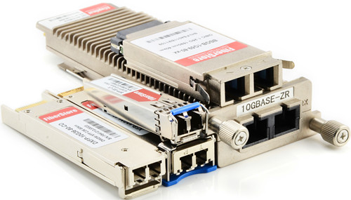
xfp transceiver

XFP transceiver module is a hot pluggable component for high speed computer network and telecommunication links that use optical fibre. It can be applied in the application of 10 Gigabit Ethernet and DWDM fibre optic networks. XFP transceiver module is a protocol autonomous optical translation device. The main feature of XFP transceiver module is that it can support 9.95Gb/s to 11.1 Gb/s data rate, transmission distance up to 80 km and operating temperature range is 0°C~70°C. Today, many kinds of XFP transceivers are available in the market, such as 10GBASE-LR XFP, 10GBASE-ER XFP, 10GBASE-SR XFP, 10GBASE-ZR XFP. See how far each XFP transceiver module can support.

10GBASE-LR XFP: the maximum distance is 10 kilometers over 1310 SMF;
10GBASE-ER XFP: the maximum distance is 40 kilometers over 1310 SMF;
10GBASE-ZR XFP: the maximum distance is 80 kilometers over 1310 SMF;

The most popular and widely used is 10GBASE-SR XFP transceiver module which has a working distance of 300 meters maximum via OM3 MMF.

Since the development of internet shopping, you can buy a transceiver from local store or from the internet. But the question is how to make sure that you can buy a high quality transceiver as there are so many online shops? Two most widely used and reliable brands of transceivers are Cisco and Juniper. Before making your decision, try to read the reviews on the web and testimonials from people who have used these brands. That will help a lot.

However, the brands are too expensive. There are various companies who develop 10G XFP transceiver module. And those are called the third party transceivers. So maybe you can choose compatible brands which have the same functions and ideal compatibility ideal for Cisco, Juniper, etc.. These XFP transceiver modules are also developed on the basis of international industrial standards and are severely checked for compatibility with tools and devices from large organisations in industry. The most important is that the price of compatible XFP transceiver module is extremely low!

FS.COM is one of the companies which have cost-effective XFP transceiver module. We provide 10GBASE-LR XFP, 10GBASE-ER XFP, 10GBASE-SR XFP, 10GBASE-ZR XFP, Bidi XFP, CWDM XFP, DWDM XFP. All XFP transceivers have gone through quality assurance test program to realise full compatibility. Compatible brands include Cisco, Juniper, Brocade, HP, Netgear, etc.. For more information about XFP transceivers, please read the article: XFP Transceiver Module.

QSFP+ Direct Attach Copper Cables for EX Series Switches

Quad small form-factor pluggable plus (QSFP+) direct attach copper (DAC) cables are suitable for in-rack connections between QSFP+ ports of EX Series switches. They are suitable for short distances of up to 10 metres, making them ideal for highly cost-effective networking connectivity within a rack and between adjacent racks. This article will introduce EX Series switches and QSFP+ DAC for EX Series switches.

Introduction to EX Series Switches

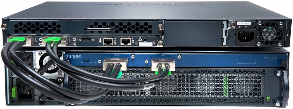
EX Series switches deliver scalable port densities and carrier-proven high availability features that consolidate legacy switch layers, helping to reduce capital and operational expenses and advance the economics of networking. For example, the EX 4200 series Ethernet switches with Virtual-Chassis technology, deliver the same Gigabit Ethernet (GbE) and 10GbE port densities as traditional chassis-based switches, but at one-eighth the footprint and less than one third the cost. The EX Series switches are right-sized for campus, data centre and remote office environments and feature many of the same carrier-class hardware and software architectures found in core routers that were purpose-built to support the convergence of data, voice, and video onto a single always-on network.

EX 4200 Series switch

By alleviating the cost, complexity and risk associated with legacy switch infrastructures, the EX Series switches enable high-performance businesses to deploy a high-performance network infrastructure based on three key tenets – operational simplicity, carrier-class reliability, and integration and consolidation – to enable ubiquitous access to strategic assets, reduce network downtime and enhance overall security to shared assets across the extended enterprise.

QSFP+ DAC Specifications

QSFP+ direct attach copper (DAC) cable is hot-removable and hot-insertable. QSFP+ DAC mainly has two kinds. One is a cable that connects directly into two QSFP+ modules, one at each end of the cable. The cables use integrated duplex serial data links for bidirectional communication and are designed for data rates up to 40 Gbps. The other is a breakout cable consisting of a QSFP+ transceiver on one end and four SFP+ transceivers on the other end. The QSFP+ transceiver connects directly into the QSFP+ access port on the QFX Series device. The cables use high-performance integrated duplex serial data links for bidirectional communication on four links simultaneously. The SFP+ links are designed for data rates up to 10 Gbps each.

The following table describes the software support for QSFP+ passive DAC cable lengths on EX Series switches for Junos OS releases.

Switch

Software Support Added

DAC Model Number

EX44300 switches

Junos OS for EX Series switches, Release 13.2X51-D15 or later

EX4300 switches

  • EX4300-24T, EX4300-24P, EX4300-48T, EX4300-48T-AFI, EX4300-48P,
    EX4300-48T-DC, and EX4300-48T-DC-AF switches—Junos OS for EX Series switches, Release 13.2X50-D10 or later
  • EX4300-32F switches—Junos OS for EX Series switches, Release 13.2X51-D15 or later
  • EX4300-24T-S, EX4300-24P-S, EX4300-32F-S, EX4300-48T-S,
    and EX4300-48P-S switches—Junos OS for EX Series switches, Release 13.2X51-D26 or later
  • EX-QSFP-40GE-DAC-50CM
  • QFX-QSFP-DAC-1M
  • QFX-QSFP-DAC-3M
  • JNP-QSFP-DAC-5M

EX4550 switches

  • EX4550-32T-AFI, EX4550-32T-AFO, EX4550-32T-DC-AFI, EX4550-32T-DC-AFO,
    EX4550-32F-AFI, EX4550-32F-AFO, EX4550-32F-DC-AFI, and EX4550-32F-DC-AFO switches—Junos OS for
    EX Series switches, Release 13.2X50-D10 or later
  • EX4550-32F-S switches—Junos OS for EX Series switches, Release 12.3R5 or later
  • EX-QSFP-40GE-DAC-50CM
  • QFX-QSFP-DAC-1M
  • QFX-QSFP-DAC-3M
  • JNP-QSFP-DAC-5M
Conclusion

QSFP+ direct attach copper cables can provide cost-effective and reliable 40G speed connections for EX Series switches with distances reaching up to 10 metres. As the leading fibre optical manufacturer in China, FS.COM offers a wide selection of QSFP+ DAC with low cost but high performance. In addition, 10G SFP+ to SFP+ DAC (eg. HP JD096C), 25G SFP28 to SFP28 DAC, 40G QSFP+ to 4 XFP DAC, 100G QSFP28 to QSFP28 DAC, 100G QSFP28 to 4 SFP28 DAC are also available for your choice. All these DACs are with 100% compatibility and can be customised according to your special requirements.

How Does Fibre Optic Loss Occur?

Data transmission through fibre optic cable has many advantages over other transmission media such as copper cable or radio. Compared with other transmission media, fibre optic cable is lighter, smaller and more flexible with faster speed over long distance. However, there are some factors influencing the performance of fibre optic cable. Fibre optic loss is an important factor to be considered when selecting and installing cables. This article will introduce detailed information about fibre optic loss.

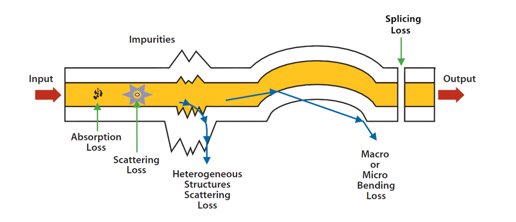
When a beam of light carrying signals travels through the core of fibre optic cable, the light will become weaker. That means the signals will be weaker. This phenomenon is called fibre optic loss or attenuation. The decrease in power level is described in dB. To transmit optical signals smoothly and safely, fibre optic loss must be decreased. Fibre optic loss is caused by internal reasons and external causes, which are also known as intrinsic fibre core attenuation and extrinsic fibre attenuation.

loss-in-fiber-optic

Intrinsic Fibre Core Attenuation

Internal fibre optic loss, also usually called intrinsic attenuation, is caused by the fibre optic cable itself. There are two causes of intrinsic attenuation. One is light absorption and the other one is scattering.

Light absorption is a major reason of fibre optic loss during optical transmission. Light is absorbed in the fibre by the materials of fibre optic cable. So light absorption is also known as material absorption. The lost power actually transferred into other forms of energy like heat because of molecular resonance and wavelength impurities. Atomic structure lies in any pure material and they absorb selective wavelengths of radiation. More over, we can’t find total pure materials in the market. So manufacturers use germanium and other materials with pure silica to optimise the fibre optic core performance.

The scattering of light is caused by molecular level irregularities in the glass structure. The light scatters in all direction. Some of them keeps traveling in the forward direction. And the light not scattered in the forward direction will be lost in the fibre optic link. Thus, to reduce fibre optic loss caused by scattering, the fibre optic core should be almost perfect and the fibre optic coating and extrusion should be carefully controlled.

Extrinsic Fibre Attenuation

Extrinsic fibre attenuation is also an important factor influencing the performance of fibre optic cable. It’s usually caused by improper handling of fibre optic cable including bend loss and splicing loss.

Bend loss is generally caused by fibre optic bend. There are two kinds of bending: micro bending and macro bending. Macro bending refers to a large bend in the fibre (with more than a 2 mm radius). To reduce fibre optic loss, you should better notice the followings:

  • Fibre core deviate from the axis;
  • Manufacturing defects;
  • Mechanical constraints during the fibre laying process;
  • Environmental variations like the change of temperature, humidity or pressure.

bend-loss

Fibre optic splicing is another cause of extrinsic fibre attenuation. It’s very common to splice fibre optic cable. So the splicing loss can’t be avoided but can be reduced with proper handling ways. For example, you can choose high quality fibre optic connectors and fusion splicing machine.

There are many factors causing fibre optic loss. To reduce the intrinsic fibre core attenuation, you should select good quality fibre optic cable. To reduce extrinsic fibre attenuation, you should better need proper handling and skills.

Maintaining MPO/MTP Polarity

The local area network (LAN) campus and building backbones as well as data centre backbones are migrating to high cabled fibre counts to meet system bandwidth needs and provide the highest connectivity density. So manufacturers start to produce MPO/MTP high density cables. Then many network designers are turning to MPO/MTP trunk cable to get the highest connectivity density for an easy migration from 10G to 40/100G. To ensure reliable system performance as well as support ease of installation, maintenance and reconfiguration, MPO/MTP cables require unique polarity design. But how to maintain proper MPO/MTP polarity?

Optical fibre links typically require two fibres to make a complete circuit. Optical transceivers have a transmit side and receive side. In any installation, it is important to ensure that the optical transmitter at one end is connected to the optical receiver at the other. This matching of the transmit signal (Tx) to the receive equipment (Rx) at both ends of the fibre optic link is referred to as polarity. In traditional cabling systems, single fibre connectors such as LC, SC are used. So it’s easy to main the polarity as long as the A side of one connector pair matches to the B side of the other connector pair in any patch cord or permanent link. However, pre-terminated, high-density cabling systems based on MPO/MTP array connectivity require a new set of design rules and have their more complicated requirements for maintaining proper polarity. Before talking about maintaining MPO/MTP polarity method, we will first introduce MPO/MTP array connectors.

MPO/MTP Array Connectors

MPO/MTP array connectors terminate multiple fibres in a single high-density interface. 4-, 6-, 8-, 12-, 24-, 36- and 72-fibre connectors are available. But 12-fibre array connectors are the most common. MPO/MTP array connectors are employed in high-density permanent link installations and can be found in pre-terminated cassettes, trunk and hydra cable assemblies used extensively in data centres.

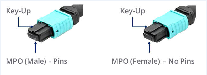
MPO/MTP array connectors are pin and socket connectors (as shown in the following picture), requiring a male side and a female side. Cassettes and hydra cable assemblies are typically manufactured with a Male (pinned) connector. Trunk cable assemblies typically support a Female (unpinned) connector. To ensure proper end-face orientation during mating process, connectors are keyed. When the key is at the bottom, it’s called key down. When the key is on the top, it’s called key up. Under the situation of key up, the fibre holes in the connector is numbered from left to right as P1, P2… There is a white dot on one side of the connector to identify where the P1 is.

mpo-mtp-connector

Three Polarity Methods

The following will introduce three different methods to maintain polarity for systems using MPO/MTP optical connectivity. Defined by TIA/EIA-568-B.1-7, these methods include installation and polarity management practices, and provide guidance in the deployment of these types of fibre array links.

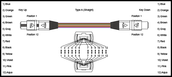
Method A

Method A employs Key Up to Key Down adapters to connect the array connectors. In this straight through configuration, Fibre 1 (P1) in the near end cassette mates to Fibre 1 (P1) in the trunk cable assembly. That is to say fibres at each end of the cable have the same position. Method A provides the simplest deployment for single-mode and multimode channels, and can easily support network extensions.

Method-A

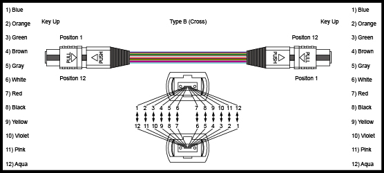
Method B

Method B uses Key Up to Key Up Adapters. The fibre circuit is completed by utilizing straight patch cords at the beginning and end of the link, and all of the array connectors are mated Key Up to Key Up. In this method, the fibre positions are reversed. Fibre 1 is mated with fibre 12, Fibre 2 mated with Fibre 11… To ensure proper transceiver operation with this configuration, one of the cassettes needs to be physically inverted internally so Fibre 12 is mated with Fibre 1 at the end of the link. This method is more complicated than method A to manage the polarity of links. As you should identify where the actual inversions need to occur. And it also requires two separate cassettes or special labeling and management of the cassettes on one end are flipped. What’s more, this method doesn’t easily accommodate angled polished (APC) single-mode connectors.

Method-B

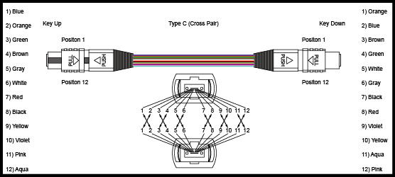
Method C

Method C uses Key Up to Key Down Adapters. This method uses straight patch cords and the same cassettes as in Method A. The difference is that the flip does not happen in the end patch cords but in the array cable itself. for example, Fibre 1 on one end is shifted to Fibre 2 at the other end of the cable. The Fibre 2 at one end is shifted to Fibre 1 at the opposite end etc. So it’s also complicated to properly manage the polarity of the links and to identify where the actual flipped array cord is placed in the link. Besides, it’s hard to extend the links. So this method is not suitable to be applied with emerging 40Gbps standards.

Method-C

Conclusion

There are three methods to maintain MPO/MTP polarity. Network designers should evaluate each method before implementing to ensure the reliability, ease of installation, maintenance and reconfiguration as well as easy migration to higher data rates solutions like 40/100G Ethernet. It’s recommended that a method selected should better not be changed in an installation.