Monthly Archives: March 2016

Optical Fibre Selection for Network Interconnection

The emergence of Data Centres, Setorage Area Networks and other computing applications drives the needs for ultra-high speed data interconnections and structured cabling. The interconnect media choices include wireless technology, copper cable and optical fibre cable. Fibre cable offers the highest bandwidth and supports the highest data rates. There are single-mode and multimode fibre types. Different types of fibre connect with fibre optic transceivers resulting in different performances and costs. So it’s important for the network designers to understand the fibre types and select the right fibre and corresponding fibre optic transceivers for network interconnection.

Optical Fibre Types

There are three main types of optical efibre suitable for network interconnection use:
9/125μm Single-mode fibre
50/125μm multimode fibre
62.5/125μm multimode fibre

optical-fiber-types

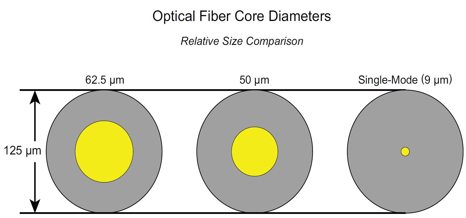
The above numbers respectively mean the diametre of the glass core where the light travels and outside glass cladding diamere which is almost the same to most fibre types. So the difference of each fibre type is caused by the core diametre. It has great impact on system performance and system cost when balanced against network application needs. Two primary affected factors are attenuation and bandwidth.

Factors Affected by the Fibre Core Diametre

Attenuation is the reduction of signal power, or loss, as light travels through an optical fibre. Fibre attenuation is measured in decibels per kilometre (dB/km). The higher the attenuation, the higher rate of signal loss of a given fibre length. Single-mode fibres generally operate at 1310 nm (for short range) while multimode fibres operate at 850 nm or 1300 nm. Attenuation is not usually considered to be the main limiting factor in short rang transmissions. But it can cause big differences in high speed network such as 100Gb/s.

Bandwidth means the carrying capacity of fibre. For single-mode fibre, the modal dispersion can be ignored since its small core diametre. Bandwidth behavior of multimode fibres is caused by multi-modal dispersion during the light traveling along different paths in the core of the fibre. It has an influence on the system performance and data rate handling. Multimode fibre uses a graded index profile to minimize modal dispersion. This design maximizes bandwidth while maintaining larger core diametres for simplified assembly, connectivity and low cost. So manufacturers start to develop higher-performance multimode fibre systems with higher bandwidth.

System Costs: Single-mode and Multimode Fibres

A fibre optic transceiver usually consists the optical light sources, typically LED–light emitting diode and optical receivers. Since the core diametre size and primary operating wavelengths of single-mode fibre and multimode fibre are different, the associated transceiver technology and connectivity will also be different. So is the system cost.

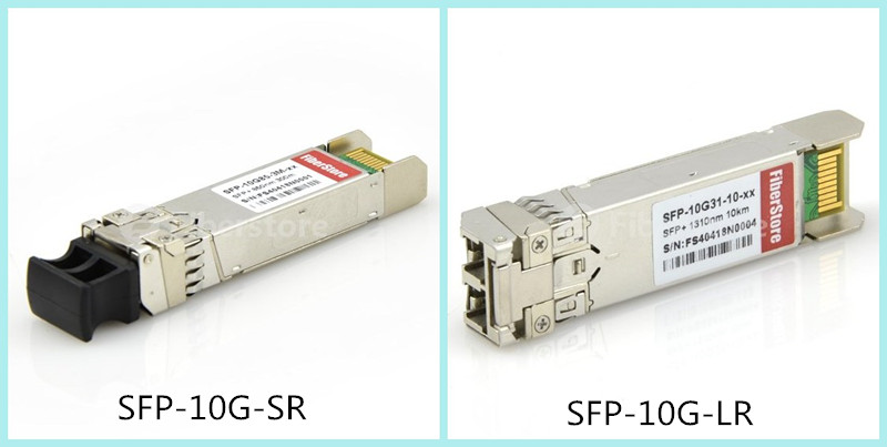
To utilize the single-mode fibres generally for long distance applications (multi-kilometre reach), transceivers with lasers such as SFPP-10GE-LR (an SFP+ 1310nm 10 km transceiver supporting single-mode fibres) that operate at longer wavelengths with smaller spot-size and narrower spectral width. But these kinds of transceivers need higher precision alignment and tighter connector tolerance to smaller core diametres. Thus, it causes higher costs for single-mode fibre interconnections. To lower the cost, manufacturers produce transceivers based on VCSEL (vertical cavity surface emitting laser), for example, 10G-SFPP-SR (an SFP+ 850nm 300m transceiver supporting multimode fibres), which are optimised for use with multimode fibres. Transceivers applying low cost VCSEL technology to develop for 50/125μm multimode fibres, take advantage of the larger core diametre to gain high coupling efficiency and wider geometrical tolerances. OM3 and OM4 multimode fibres offer high bandwidth to support data rates from 10Mb/s to 100Gb/s.

Conclusion

Optical fibre is an easily-installed medium that is immune to electromagnetic interface and is also more efficient in terms of power consumption. What’s more, fibre optic cable can save space and cost with higher cabling density and port density over copper cabling. For single-mode fibre and multimode fibre, each one has its advantages and disadvantages. Network designers should better select the right fibre type and related fibre optic transceivers according to specific situations for higher system performance. Of course, cost is another important factor to be considered.

To Upgrade from 10G to 40G or not?

Some enterprises have built 10G network links. But one can never imagine how fast the network traffic is growing. There are many factors influencing the needs for high bandwidth, such as the rising populations of network subscribers, business and personal competitiveness, and the use of more video. In that way, 10G network is not able to meet the increasing needs. Then it pushes optical backbones and metro core networks to move to 40G network. However, to move to the high capacity network, many difficulties must be encountered in optical fiber networks. The question is to upgrade to 40G or not?

Difficulties of Upgrading to 40G

Cost Increases

The first challenge some service providers face when they consider moving to 40G technology is the cost of equipment. That’s the same when considering upgrading from 2.5G to 10G. The price of a 40G link is expensive than that of 4*10G links (as shown in Figure1). Equipment is one of the price determining factors. For example, a QSFP transceiver (the average market price of a JNP-QSFP-40G-LX4, Juniper Compatible 40GBASE-LX4 QSFP+ Transceiver, is more than US$ 2000.00) is more expensive than 4 SFP+ transceivers. And some equipment may not be suitable for 40G networks, which means brand-new expensive equipment are needed.

10G-to-40G

Figure1. 10G to 40G

Optical Signal to Noise Ratio (OSNR) Drops

A unit of information, called a symbol, transmitted at 10G takes 100 pico seconds (100ps), and that symbol transmitted at 40G takes 25ps. This means the receiver translating the light back into a symbol deals with only 25% of the light of a 10G symbol. It causes 6 dB OSNR to drop. The OSNR is a measure of the strength of the signal. So the drop of 6dB means the link length will be decreased by 75%.

Chromatic Dispersion (CD) Increases

When a signal travels through a fiber, CD causes the pulses constituting the signal to spread in time. If this spreading is not compensated, these pulses will overlap. It means the signal is unusable. Comparing to 10G, this effect is 16 times more obvious at 40G. This creates a serious roadblock for 40G system operating.

Polarization Mode Dispersion (PMD) Increases

PMD is another problem which may be the most difficult to solve. This occurs due to infinitesimal imperfections in the circularity of the core of a fiber, which may be caused by the material itself, manufacturing process, or stress in the field created by bending or twisting. PMD is more capricious than predictable, and is very dependent on the qualities of the fiber. PMD can be influenced by factors including cable age or vintage, temperature of cable, cable design and cable manufacturer, etc.

Methods to Overcome Those Difficulties

To achieve 40G, new modulation schemes and approaches are being developed. The following tells about methods to overcome those difficulties.

Save Cost

We can discuss it from two sides: to buy or not to buy new equipment. First, to buy new equipment. As mentioned above, some optical equipment like transceivers from Google searching result are quite expensive. Thanks to the fast developed technology, manufacturers like Fiberstore (FS.COM) produce many compatible brands of which the price is quite low. The price of FS.COM JNP-QSFP-40G-LX4 is US$ 400.00. Compared with the average market price, it’s obvious that FS.COM products have advantages on price. Now you may doubt that transceivers with such a low price will not have good quality. Then you don’t need to worry about it when you see FS.COM test assured program which provides world-class customer confidence in each fiber optics. Except transceiver optics module, FS.COM also has other cost-effective optical products for you to upgrade to 40G network.

Second, not to buy new equipment. Consider that many enterprises have spent a lot investments in 10G networks, many carriers would like to upgrade to 40G by just inserting new 40G cards into their existing 10G WDM systems to save cost. Here are three advisable strategies moving from 10G to 40G: Use the current fiber plant of the 10G routes, and not invest in expensive deployments of new fiber for 40G; Add 40G to currently installed equipment, so additional equipment is not required to sit alongside the 10G gear; Keep the network robustness and architecture intact, that is, the current line design, so that the numbers of OADM and ROADM nodes on any pathway in a ring or mesh do not need to be reduced.

Improve OSNR, CD, PMD

Problems related to OSNR, CD and PMD are caused by optics, the fiber quality and other optical equipment on one side. So you should better choose high quality equipment. On the other side, it depends on advanced optical technology bringing about simplified materials and better methods.

Conclusion

Although there are many challenges, the trend of upgrading from 10G to 40G is inevitable. With the above methods and more advanced fiber optical technologies, you should upgrade to 40G network without any hesitation. Besides, to help customers to achieve 40G smoothly, FS.COM researches and develops high-quality products with favorable price. And FS.COM will keep providing customers with more cost-effective equipment and better solutions to realize 40G upgrading.

What Should We Know Before Deploying 10 Gigabit Ethernet Cable?

Since the need for high data speed increases and the price of optical equipment becomes more affordable, many enterprises start to deploy 10 Gigabit Ethernet cables in their cooperate backbone, data centres to support high-bandwidth applications. But what should we know before deploying 10 Gigabit Ethernet cables?

Fibre Choices for Deploying 10 Gigabit Ethernet Cable

Three factors should be considered for fibre cable deployment: fibre cable type, 10 Gigabit Ethernet physical interface and fibre optical transceiver module. The following tables show the standard fibre cables, physical interfaces, and transceiver module applicable to 10 Gigabit Ethernet.

Fibre Cables Multimode OM1 fibre (62.5/125 μm)
OM2 fibre (50/125 μm)
OM3 fibre (50/125 μm)
Single mode 9/125 μm fibre
Physical Interfaces 10GBase-LRM Max distance 220m
10GBase-S Max distance 300m
10GBase-L Max distance 10km
10GBase-E Max distance 40km
10GBase-Z Max distance 80km
Transceiver modules XENPACK Large form factor
X2 Smaller than XENPACK
XFP Smaller than X2
SFP+ Smallest form factor

Note: the 10 Gigabit Ethernet physical interface type should be the same on both ends of the fibre link. For example, it is OK to deploy a fibre link with one XFP-10G-MM-SR optics on the left, and one SFP-10G-SR optics on the right. However, one SFP-10G-SR optics and one SFP-10G-LRM optics can’t connect together because of different physical types.

Copper Choice for Deploying 10 Gigabit Ethernet Cable

As switching standards copper cabling standards develop, copper cabling for 10GbE is more widely used. There are three different copper technologies for deploying 10 Gigabit Ethernet cables. Each one has different performances and prices.

First, 10GBase-CX4 is the first 10 Gigabit Ethernet copper cable standard. It’s relatively economical and allows for very low latency. But the form factor is too large for high density port counts in aggregation switches.

Second, Small Form-factor Plus (SFP+) is the latest standard for optical transceivers. 10 Gb SFP+Cu Direct attach cables (DAC) directly connect into an SFP+ housing. It’s the best copper solution for servers and storage devices because it has low latency, small form factor and reasonable price.

Third, 10GBase-T is a fully IEEE compliant Ethernet transport technology standard, as defined by IEEE 802.3an-2006. 10GBase-T is to run 10 Gigabit Ethernet over CAT6a and CAT7 copper cabling up to 100 metres. 10GBase-T copper twisted-pair cabling can enable the earlier 10MB, 100MB and 1GB operation. However, 10GBase-T still needs to be improved on its price, power consumption and latency.

Media Copper cable Range (max) Average Latency
CX4 Twinax 15m (49ft) 0.1 μs
SFP+ DAC Twinax SFP+CU 10m (33ft) 0.1 μs
10GBase-T CAT6 RJ45 30m(98ft)—50m (164ft) >1.5 μs
CAT6a RJ45 100m (98ft) >1 μs
CAT7 GG45 100m (98ft) >1 μs
SFP+ Direct Attach Cables

SFP+ DAC cable integrates SFP+ compatible connectors with a copper cable into a low-latency, energy-efficient, and low-cost solution. SFP+ direct attach cables offer the smallest 10 Gigabit form factor and a small cable diametre for higher density and optimised rack space in 10 Gigabit Ethernet (GbE) uplinks and 10 Gigabit Fibre Channel SAN and NAS input/output connections. To use SFP+ direct attach cables can save you a lot compared with fibre optic solutions. And it can still provide lower latency and save up to 50% power consumption per port than other copper twisted-pair cabling systems.

sfp+ dac

SFP+ direct attach cables can also provide enhanced scalability and flexibility. The cables connect several servers or storage devices together in a single rack. Thus, it reduces the use of intermediate patch panels. And it’s easy to move racks or deploy one rack at a time since the cabling outside of the rack is limited to the main switch connection.

FS offers comprehensive solutions for 10 Gigabit Ethernet cabling, including fibre cables, copper cables, and SFP+ direct attach cables and each one has various subcategories. Before deploying 10 Gigabit Ethernet cables, you need to consider factors of the performance, cost, power consumption and latency and choose the most suitable cabling solution.

Related Article: Cisco SFP-10G-SR: All You Need to Know

Brief Introduction for 10 Gigabit Ethernet

The demand for high bandwidth promotes the development of data transmission technology. Ethernet standard continuously evolves to meet fast speed need, from 100BASE, 1000BASE to 10 Gigabit Ethernet. Meanwhile, the data carrying technology also develops to provide great bandwidth for transporting data with low cost, such as the copper and fibre cable as well as optical transceiver module.

10 Gigabit Ethernet Cabling
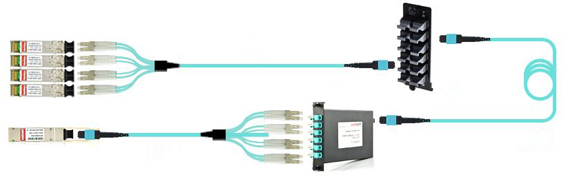
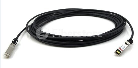
Figure1. 10 Gigabit Ethernet Cabling

Media for 10 Gigabit Ethernet: Copper and Fibre

In 10 Gigabit Ethernet, copper and fibre are used to transport data. Each one has its own advantages and disadvantages.

Copper is more affordable and easy to install. It acts the best when used in short lengths, typically 100 meters or less. But when deployed over long distance, electromagnetic signal characteristics will influence its performance. Besides, bundling copper cabling can cause interference, which makes it difficult to employ as a comprehensive backbone. So copper cabling are widely used in PCs and LANs communication network instead of campus or long-distance transmission.

Compared with copper, fibre cabling is usually used for long distance communication among campus, and environments that need protection from interference, such as manufacturing areas. In addition, fibre cabling is more reliable and less susceptible to attenuation, which makes it suitable for data transmission distance over 100 meters. But fibre still has drawbacks. It’s more costly than copper.

The Evolution of 10 Gigabit Ethernet Cabling

Since 10 GbE technologies have changed, so have the cabling technologies. There are two main standards: IEEE802.3ae and IEEE802.3ak. Factors covered in these standards like transmission distance and equipment being used are helpful to determine the cabling strategy.

  • IEEE802.3ae

IEEE802.3ae standard updates the existing IEEE802.3 standard for 10GbE fibre transmission. The new standard defines several new media types for LAN, metropolitan area network (MAN) and wide area network (WAN) connectivity.

10GBASE-SR – it supports 10GbE transmission over standard multimode fibre (850 nm) for distances of 33 and 86 meters. The SR standard also supports up to 300 meters using the new 2000MHz/km multimode fibre (laser optimized). This one is the lowest-cost optics for 10GbE.

10GBASE-LR – it uses optics (1310nm) and supports single-mode fibre up to 10 km.

10GBASE-LX4 – it can support multimode fibre for distances up to 300 meters using Coarse Wavelength Division Multiplexing (CWDM). The LX4 standard also supports single mode fibre for up to 10 Km. LX4 is more expensive than both SR and LR because it requires four times the optical and electrical circuitry in addition to optical multiplexers.

10GBASE-ER – it uses optics (1550nm) to support single mode fibre up to 30 km.

  • IEEE802.3ak / 10GBASE-T

10GBASE-T is the latest proposed 10GbE standard for use with unshielded twisted-pair (UTP) style cabling. This standard is to improve the performance and increase the transmission distance at a lower cost. Category 5 (Cat 5) and Category 6 (Cat 6) are the most common cabling systems being installed today. But Cat 5 can’t meet the bandwidth demands of 10GbE’s transmission. To meet the needs of 10GbE, manufacturers create Category 6A (Cat 6A), designed with existing Cat 6 cable but measured and specified to higher frequencies. In addition to Cat 6A, 10GBASE-T will operate on Category 7 (Cat 7) cables.

10GbE Transceivers

Except the cabling, transceivers also need to be considered for the network connectivity. Transceivers provide the interface between the equipment sending and receiving data. 10GbE has four defined transceiver types, including XENPAK, X2, XFP and SFP+ (Small Form-factor Pluggable Plus). These transceivers are pluggable and are compliant with 802.3ae standard.

Among them, SFP+ is the smallest 10G form factor. And it can interoperate with XENPAK, X2, XFP interface on the same link. Fiberstore provides a number of interfaces attempted to satisfy different objectives including support for MMF and SMF compatibility, such as SFP-10G-SR, SFP-10G-LR, SFP-10G-ER, SFP-10G-ZR, etc. For example, SFP-10G-SR transceiver module can support 300 meters data transmission distance over 850 nm multimode fibre. And SFP-10G-LR module supports the link length up to 10 kilometers over 1310 nm single mode fibre.

10 Gigabit Ethernet Transceiver

Figure2. 10 Gigabit Ethernet Transceiver

As the corresponding cabling technology gets great improvement, 10 Gigabit Ethernet is becoming more affordable and pervasive. 10G network brings us higher speed. For 10G network connectivity, SFP+ transceivers are recommended to transport data over copper or fibre cabling.

Related Article: Cisco SFP-10G-SR: All You Need to Know

Do You Know about QSFP LR4 PSM?

40GBASE QSFP+ (Quad Small Form-Factor Pluggable) transceivers are widely provided all round the world. These modules offer various high-density and low-power 40 Gigabit Ethernet connectivity options for data centre, high performance computing networks, enterprise core and distribution layers and service provider applications. Among so many options, such as QSFP-40G-SR4, QSFP-40G-LR4, QSFP-40G-ER4, WSP-Q40GLR4L, etc., QSFP-40G-LR4 is well know as it can support link lengths of up to 10 km over single mode fibre. It enables high-bandwidth 40G optical links over 12-fibre parallel fibre terminated with MPO/MTP multifibre female connectors. The following will talk about one of QSFP-40G-LR4: QSFP LR4 PSM (Parallel Single Mode).

Main Features of QSFP LR4 PSM

The QSFP LR4 PSM is a parallel 40G Quad Small Form-Factor Pluggable optical module. It offers increased port density and saves cost for total system. This module provides 4 independent transmit and receive channels. It can support 4×10 Gbps operation for an aggregate data rate of 40 Gbps on 10km of single mode fibre. It can also support 1x40G optical links over 12-fibre parallel fibre terminated with MPO/MTP connectors. But the ribbon cable with MPO/MTP connector should have proper alignment instead of being twisted. The module operates with single +3.3 V power supply. With a 2-wire serial interface, it allows to send and receiver more complex control signals and to receiver digital diagnostic information. If there are some channels not used, then the unused channels can be shut down for maximum design flexibility. This transceiver module with form factor, optical/electrical connection and digital diagnostic interface is compliant with Multi-Source Agreement (MSA). It can meet the harshest external operating conditions including temperature, humidity and EMI interference (Electromagnetic Interface). For example, its operating case temperature ranges from 0 to 70 ℃。

Working Principle of QSFP LR4 PSM

This QSFP LR4 PSM is a parallel single mode optical transceiver with an MTP/MPO fibre ribbon connector. This transceiver module offers 4 transmit and 4 receive channels and each can support 10.3125 Gbps data rates (as shown in the following figure). The transmitter accepts electrical input signals compatible with Common Mode Logic (CML) levels. All input data signals are differential and internally terminated. The receiver converts the input signals via a photo detector array into parallel electrical output signals. And the outputs signals are also voltage compatible with Common Mode Logic (CML) levels. All signals are differential and support a data rates up to 10.3 Gbps per channel.

function-diagram of QSFP LR4 PSM

Each module offers 7 low speed hardware control pins (including the 2-wire serial interface): ModSelL (Module Select), SCL (Serial Clock), SDA (Serial Data), LPMode (Low Power Mode), IntL (Interrupt), ResetL, and ModPrsL (Module Present). Here just introduces several pins.

ModSelL is an input pin. When held low by the host, the module responds to 2-wire serial communication commands. The ModSelL allows the use of multiple QSFP+ modules on a single 2-wire interface bus–individual ModSelL lines for each QSFP+ module must be used.

SCL and SDA are required for the 2-wire serial bus communication interface and enable the host to access the QSFP+ memory map.

LPMode pin is used to set the maximum power consumption to protect the host. If the hosts are able to cool higher power modules, such modules will be accidentally inserted.

FS.COM QSFP-40G-LR4 is designed for use in 40 Gigabit Ethernet links over single mode fibre. It’s compliant with QSFP+ MSA and IEEE 802.3ba 40GBASE-LR4. LR4 PSM is one of QSFP-40G-LR4 modules. All these cost-effective transceivers have to be tested before shipping to ensure full compatibility and to offer the best customer service.