Monthly Archives: May 2015

Basic Knowledge about Ethernet

Nowadays, billions of file cabinets and mountains of papers stored in computers need to be transmitted at high speed with great efficiency. Computer networking technologies are key to meet this demand, allowing computers on the internet to send and receive information easily. This article will introduce the network technology: Ethernet which is widely used nowadays.

Ethernet is a family of computer networking technologies for local area networks (LANs) and metropolitan area networks (MANs), connecting more than 85 percent of the world’s LAN connected PCs and workstations. It is a link layer protocol in the TCP/IP stack, describing how networked devices transmit data on the same network segment and how to put data out on the network connection. Ethernet was commercially released in 1980 and first standardized in 1983 as IEEE 802.3. Its standards have been updated to embrace new media, higher transmission speeds and changes in frame content such as the new standard 802.3af defining Power Over Ethernet [POE] crucial to most Wi-Fi and IP telephony deployments.

Ethernet

Ethernet was initially designed to run over coaxial cables but has been updated to used for twisted pair cables and fibre optical fibres over years. The most commonly installed Ethernet systems are called 100 BASE-T (the “BASE-T” part means the systems use twisted-pair cabling) which provides transmission speeds up to 100Mbps. It is typically used for LAN backbone systems, supporting workstations with 10BASE-T cards. Another widely used one is Gigabit Ethernet which is primarily carried on optical fibre with very short distances possible on copper media. It provides an even higher level of backbone support at 1000 Mbps or 1 Gbps. With the increasing of data transfer rates, the standards: 10 Gigabit Ethernet and 100 Gigabit Ethernet are available. Their data rates reached up to 10 gigabits per second and even 100 gigabits per second respectively, making them be good solutions to deliver high bandwidth in LANs.

QQ截图20150525174629

100GBASE-LR4 CFP2 Optical Transceiver Module

It is concluded that Ethernet has evolved to provide excellent performance and network intelligence. As Ethernet data transfer rates are excepted to be increased to 400 Gbit/s by early 2017, Ethernet will be the most potential network technology in the future for its high-speed data transmission.

Fiberstore offers a wide range of products for 10GbE or 100 GbE applications such as the new product: 100GBASE-LR4 CFP2 Optical Transceiver module. The optical transceiver offers smaller size and lower power consumption for data centre networking, enterprise core aggregation, and service provider transport applications. For more information, please visit www.fs.com.

CWDM Cost Efficient Transport in Short-haul Networks

CWDM-technology

CWDM Technology

In the field of telecommunications, data centre connectivity, video transport, fibre optic cabling is highly desirable for today’s communication needs due to the enormous bandwidth availability. As fibre cabling is sometimes expensive for people especially individuals to use, wavelength division multiplexing (WDM) is highly advisable for it can expand the capacity of fibres. This article will depict one kind of WDM: coarse wavelength division multiplexing (CWDM or Coarse WDM) which works efficiently with lower cost in short-haul networks in comparison with DWDM (Dense WDM).

CWDM is a method of combining multiple signals on laser beams at various wavelengths for transmission along fibre optic cables. Compared to DWDM which is a more tightly packed WDM system, CWDM has larger channel spacing, having fewer wavelengths be transported on the same fibre. For instance, CWDM typically has channels at wavelengths spaced 20 nanometres (nm) apart, compared with 0.4 nm spacing for DWDM. DWDM can typically transmit from 32 to 128 channels by using erbium-doped fibre amplifiers to boost the signal over long distances, which makes it ideal for long-haul networks. In contrast, CWDM can only transmit a maximum of 18 channels with large spacing between channels, making optical amplifiers not able to be used in CWDM system. So CWDM is typically deployed at short-haul networks.

Cost-Comparison-of-WDM-Technologies

Cost Comparison of WDM Technologies

Due to its broader channel spacing, CWDM has a cost advantage over DWDM. CWDM systems spread less precise lasers over a larger range of wavelengths with consuming less power with low losses. For example, both DWDM and CWDM utilise Distributed Feedback Lasers (DFB). However, DWDM requires the larger cooled DFB lasers because laser wavelengths drift about 0.08 nm/°C with temperature. CWDM uses DFB lasers that are not cooled because laser wavelengths drift about 6nm over the range of 0-70°C and the lasers’ tolerance (extent of wavelength imprecision or variability) in a CWDM is up to ±3 nm. The use of uncooled lasers causes lower power consume, which has positive financial implications for systems operators. For instance, the cost of battery is minimized with the decreasing of power consume, which reducing operating costs.

It is concluded that CWDM is the technology of choice for cost efficiently transporting data traffic in short-haul networks. And as the demand for bandwidth is pushed to the edge of the network, the need for low-cost transport systems is imperative.

QQ截图20150518181345

CWDM Transceivers

FS offers a wide range of CWDM products such as CWDM MUX DEMUX with low cost, CWDM OADM with various configurations, CWDM Transceivers (SFP, SFP+, XFP, GBIC, X2, XENPAK) supporting 155Mbps to 10Gbps data transmissions, etc. Compatible CDWM transceivers are strongly recommended for you. There are CWDM transceivers of famous brands such as Cisco, HP, Juniper, etc. All these CWDM transceivers are of high quality and capacity to be applied to transport data traffic with low cost. For more information, you can visit FS online shop.

DWDM Techonology in Long-haul Optical Networks

In twenty-first century, there is a growing volume of data traffic which requires a higher bandwidth capacity. But this explosion in consumer demand for bandwidth makes long-haul networks cop with fibre exhaust. To respond to this explosive growth in bandwidth demand, many long-haul providers use dense wavelength division multiplexing (DWDM) technology to enhance the capacity of propagating data.

DWDM wavelength

Wave Division Multiplexing: Light in different colors can be combined on the same fibre

DWDM Solution — Efficient for Long-haul Provider

DWDM is an efficient solution for long-haul providers. It can increase the capacity of embedded fibre by first assigning incoming optical signals to specific frequencies within a designated frequency band and then multiplexing the resulting signals out onto one fibre. Compared to CWDM (coarse wavelength division multiplexing), DWDM has smaller channels spacing, enabling more signals with higher precision to be combined on the same fibre. It is typically used for long-haul system for its more channels to transport data. DWDM typically has the capability to transport up to 96 channels (wavelengths) in what is known as the Conventional band or C-band spectrum. Fiberstore provide DWDM Mux/Demux various from 4 channels to 96 channels. For better use at present and in the future, we offer plug-in FMU DWDM Mux/Demux (Check FMU DWDM Mux/Demux). With the advancement of DWDM technology, even 160 channels (wavelengths) can be transported within the same fibre, which allows as many as signals be transported simultaneously. DWDM can also combine multiple optical signals, which makes them be amplified as a group and transported in high speed and large volume. So DWDM technology is one of the best choices for transporting extremely large amounts of data traffic over metro or long distances in optical networks.

dwdm wavelength region

Wavelength Regions

DWDM Solution — Economical for Long-haul Provider

DWDM technology is also an economical solution for long-haul providers. A DWDM infrastructure can increase the distance between network elements, benefiting long-haul providers who look to reduce their initial network investments significantly. The fibre optic amplifier component of the DWDM system also enables long-haul providers to save costs without by taking in and amplifying optical signals without converting them to electrical signals. Furthermore, DWDM can provide a broad range of wavelengths in 1.55-μm region within C-band, which is showed in the picture “Wavelength Regions”. With a DWDM system multiplexing more wavelengths on a singer fibre, carriers can decrease the number of regenerators in a long-distance networks, resulting in fewer interruption and improved capacity with less loss.

Proven to be the optimal way of combining advanced functionality with cost efficient transport, DWDM technology is also friendly-used. The long-haul providers can integrate the DWDM technology easily with existing equipment in the network for the interface is bit-rate and format independent. And as continuous growth in data traffic, the long-haul providers will have an increasing reliance on improved DWDM technology to ensure good capacity of data transmission.

FS.COM DWDM Solution

Fiberstore supplies a complete series of WDM optical network solutions such as multiplexers, amplifiers, transceivers, etc. Especially, Fiberstore produce and stock for a full range of DWDM products to help build and expand fibre optic networks. For example, Fiberstore offers DWDM MUX/DEMUX Modules with 50GHz/100GHz/200GHz channel spacing, DWDM OADM modules with various configurations and DWDM Transceivers (SFP, SFP+, XFP, GBIC, X2, XENPAK) supporting 155Mbps to 10Gbps data transmissions.

Fibre Optic Cleaving

To get good fibre optic splices or terminations, especially when using the pre-polished connectors with internal splices, it is essential to cleave the fibre clearly. The term “cleaving” may be somewhat confusing. This article will give you a thorough introduction of it.

Description of Fibre Optic Cleaving

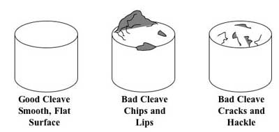
Cleaving is a process of controlled breaking of a bare fibre, which intends to create a perfectly flat endface, perpendicular to the longitudinal axis of the fibre. It begins with making a tiny scratch on the side of the fibre by using a sharp diamond, carbide or ceramic blade, before or while some defined tension or bending is applied to the fibre. Then the fibre breaks and starts at the mentioned scratch point and the scratch propagates rapidly over the full fibre cross-section, leaving a very clean surface on the obtained two fibre ends.

Note: Cleaving is not cutting just breaking in the bulk of the process. And before cleaving, a fibre coating needs to be stripped off with a coating stripper tool, or dissolved with a suitable solvent.

cleave-examples

Importance of Fibre Optic Cleaving

Cleaving is one of the important steps in the preparation for a fibre splice operation. The better results fibre cleaving has, the less splicing loss is. Otherwise, problematic cases occur. For instance, if the fibre ends are not precisely cleaved, the ends will not be mated properly. If the cleaved ends are at an angle, there will be a gap between the fibres that will cause loss in a mechanical splice or uneven fusion splicing. If there is a protrusion, or lip, on one of the fibres, the two fibres will not butt up against each other. If there are surface defects, called hackle or mist, the ends will reflect or diffuse light, causing loss.

Fibre Optic Cleaving Tools

There are two tools used for fibre optic cleaving: cleaver and pen-shaped scribe. Those two tools will be depicted in the following context to make you have a further understanding of cleaving.

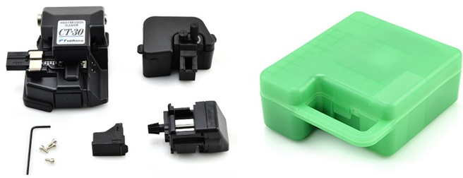
A cleaver is a tool that holds the fibre under low tension, scores the surface at the proper location, then applies greater tension until the fibre breaks. As a good cleaver is automatic and produces consistent results, the user need only clamp the fibre into the cleaver and operate its controls.

A pen-shaped scribe is typically used to remove excess fibre from the end of a connector before polishing. It looks like a ballpoint pen, but has a small wedge tip made of diamond or other hard material and applied to scratch the fibre manually. It is used with the “scratch and pull” technique. First the fibre is scribed perpendicular to its length. Then the fibre is pulled to be broken at the scribe. As conducted manually, it requires experienced operators to produce good cleaves.

ct-30 detail

For more information, please visit FS.COM or contact us over sales@fs.com.