Monthly Archives: April 2015

Fluke Networks AirCheck Wi-Fi Tester

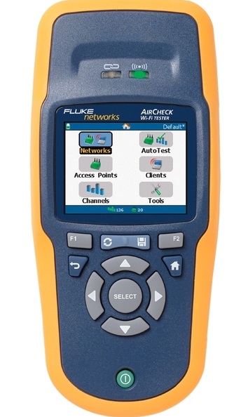
As one of the global-leading providers, Fluke offers network testers intensively trusted by leading industry professionals when they need to solve the most difficult issues and emerging challenges in data centres, mobility, and unified communications and WLAN security. This article will depict one kind of its network testers known as Fluke Networks AirCheck Wi-Fi Tester.

Introduction of Fluke Networks AirCheck Wi-Fi Tester

AirCheck Wi-Fi Tester is a simple-to-use, handheld wireless tester used for verifying and troubleshooting 802.11 a/b/g/n network availability, connectivity, and security quickly. Its intuitive interface allows you to promptly see wireless network usage and easily determine if it’s Wi-Fi traffic or non- Wi-Fi interference. It is an essential tool of checking wireless environment, enabling you to identify and locate APs whether authorized or rogue. And it can document your troubleshooting session and create professional-quality reports fully, enabling fast trouble ticket resolution or problem escalation.

Fluke network tester

Features of Fluke Networks AirCheck Wi-Fi Tester

Some features of it are listed in details, which assures that you will have a further and clearer understanding of it.

  • Supports 802.11a/b/g/n/ac with instant-on operation powering up in less than three seconds and automatically starts discovering networks, access points (APs), and channel activity
  • Get answers fast through one-button Auto Test which provides a pass/fail indication of the wireless environment and identifies common problems
  • Identifies security settings for each Network and Access Point: Open, WEP, WPA, WPA2, and/or 802.1x
  • Pinpoints Wi-Fi traffic and interference to show how much of each channe’s bandwidth is consumed by 802.11 traffic and interference
  • Connects networks or specific APs using WEP, WPA, WPA2, and/or 802.1x to verify connectivity and network access inside and outside the firewall
  • Robust and in-depth WLAN connection tests – from probing to DHCP request to ping
Fiberstore Fluke Networks AirCheck Wi-Fi Tester Solution

Fiberstore offers five modules of network AirCheck Wi-Fi testers at reasonable price with quality guarantee. Details are shown on the following sheet.

Module # Accessories Description
AirCheck–LE AirCheck Wi-Fi Tester for Law Enforcement includes: AirCheck tester, AirCheck holster, External directional antenna, Auto charger and AirCheck Getting Started Guide for Law Enforcement
ACK-LRAT2000 Network Tech Troubleshooting Kit w/ACK,LRAT-2000 includes: AirCheck tester, LinkRunner AT 2000 tester, AirCheck external directional antenna, spare Li-ion battery for either AirCheck or LinkRunner, IntelliTone Pro 200 probe, WireView 2-6 cable ids, LinkRunner AT holster, AirCheck holster and deluxe carrying case
ACK-LRAT-CIQ Ultimate Network Tech Troubleshooting Kit w/ACK,LRAT-2000,CIQ includes: AirCheck™ tester, LinkRunner AT 2000 tester, AirCheck external directional antenna, spare Li-Ion battery for either AirCheck or LinkRunner, IntelliTone Pro 200 probe, WireView 2-6 cable ids, LinkRunner AT holster, AirCheck holster and deluxe carrying case and CableIQ™ Qualification tester Fluke Networks
ES2-PRO-SX/I-ACK EtherScope Series 2 LAN WLAN SX Fibre ITO + AirCheck including: EtherScope Series 2 LAN and WLAN with fibre and ITO options; and AirCheck Wi-Fi Tester
ES2-PRO-SXI-LR-ACK EtherScope E S2 LAN WLAN SX Fibre ITO + LRPRO + AirCheck-Kit including: EtherScope E Series 2 LAN and WLAN with fibre and ITO options; LinkRunner Pro with Reflector, Lithium Ion battery, and software case; and AirCheck Wi-Fi Tester with extra Lithium Ion battery, directional antenna and hard case

Knowledge of Punch Down Tool

Introduction of Punch Down Tool

Punch down tool, also called punch down tool or krone tool (named after the KRONE LSA-PLUS connector), is a small hand tool used by telecom and data network technicians to install wiring for telephone, computer and various audio network, designing for inserting wire into insulation-displacement connectors on punch down blocks, patch panels, keystone modules, and surface mount boxes (also known as biscuit jacks). Its name is derived from the method by which the tool pushes a solid copper wire between metal blades on the connection block and cuts off the excess by punching the tool, driving the tool blade through the wire.

Applications of Punch Down Tool

Punch down tool is commonly used for termination works in the coppper network builted by twisted-pair cables like the Cat5, Cat5e, Cat6 and some newer standard Ethernet cables. With cables terminated with keystone jacks, cross-connect blocks or patch panels, networks run smoothly, enhancing working efficiency and reducing losses. For instance, it is widely used by IT staff to ensure successful connections between computers and data centre, maintaining a high level of transmission.

punch down tool

Tips When Using Punch Down Tool

Procedures

  • Hold the wire in your hand and lace it through the correct slots on the connection block. Repeat with other wires that need to be inserted in the connection block.
  • Hold the punch down tool with the blade facing down. Align the blades with the wires on the connection block.
  • Punch down the wire by holding the wire and pushing the tool firmly into the block. This should connect the wire to the terminal and cut off any excess wire at the same time.
  • Test the connection you just created. Pull on the wires to make sure they are attached properly.

Note: It is essential that the tool blade should not cut throughout the wire insulation to make contact, but rather the sharp edges of the slot in the contact post itself slice through the insulation. In addition, punch down tool is also used to cut off excessive wire in the same operation.

Warnings

  • Always wear safety glasses when using a punch down tool.
  • Models with interchangeable blades will extend the life of your tool.
  • Use the pressure adjustment screw or knob to set the tool to a comfortable level for your use.
  • Never use a punch down tool to tighten flat head screws because this can break the cutting blade.
  • Although the tool is usually made of plastic, there still is a shock hazard when working with electrical circuits.

FS.COM offers impact punch down tool with competitive price such as the 110 punch down tool, Krone punch down tool. Please visit our website or contact us over sales@fs.com

Introduction of Phone Line Tester

Description of Phone Line Tester

Phone line tester is a pockets-sized device used for basic troubleshooting of analog phone systems as well as the line polarity. It monitors phone lines for digital-tone quality and signal power, tests of correct jack polarity (detects reversed tip and ring), and indicates call addressing for correct telephone extensions.

What is Phone Line Tester Used For?

Phone line tester is mainly applied to check the operating parameters of the telephone company’s wiring at the modular connector which includes the open circuit or “on-hook” line voltage, the ringer voltage, and the polarity of the line. The phone line’s voltage conditions are indicated by a meter and the polarity of the line connections is indicated by an LED. The wires in the phone cables are colour-coded, with the green wire being the positive side, and the wire being the negative side. When there is no load on the line, that is, when all phones in your home or office are oil hook, the measured voltage at your phone’s modular connector should be greater than 40-volts DC, give or take a smidgen. And normally, polarity is normally not a problem for most standard phones will work regardless of the polarity of the DC voltage on the telephone line. However, reversed line polarity can interfere with certain kinds of switching equipment, in particular, some of the low-cost conference and multi-use switchers, so we’ve provided for that test.

How does a Phone Line Tester work?

The phone line tester shown in the following picture is connected to the phone line through modular connector P1. The tester only uses two of its four connectors-the red and the green. If it is correct-that is, if the green wire is the positive side-and the red wire is the negative side, nothing will happen. If the situation is reversed. The LED will light. With switch SI Set for LINE/RING. Both S1-a and S1-b are open and the meter indicates the condition of the line-voltage. Any line voltage reading in the LINE OK range (more on the meter in a moment) indicates a line voltage higher than 40-volts DC. If the telephone is caused to ring, either by using a ring back number or by dialing from another phone, the meter will indicate RING OK, and the LED will pulse (indicating AC), if the ringing voltage/current is correct. The actual position of the meter’s pointer depends on how ringers are connected across the line. (Three or more of the old-fashioned ringers can excessively load the ringing voltage if the local telephone company has not corrected for your ringer load.) When S1 is closed the voltage range of the meter is changed and a nominal load resistance of 230 ohms (R5 and R6) is connected across the line to emulate the off hook load of the telephone. If the meter indicates LOOP OK, you can be certain that you have sufficient loop voltage for satisfactory telephone operation. If you place another load on the line, perhaps by taking an extension telephone off hook, the meter reading will almost invariably drop below the LOOP OK range. That is perfectly normal; the line is operating properly when a single loop load results in a LOOP OK meter reading. That is how to test telephones for proper connection. If lifting the handset causes the meter reading to drop, you can at least be certain that the telephone’s hook switch is working and that the repeat coil is connected to the line.

line tester

Features of Phone Line Tester

  • Receiving and reproducing telephone system dial tone to determine the quality of the tone
  • Equipped for jack and cross-connect systems access
  • Receiving tracing signals for identifying specific conductors in a cable run (TRACE function requires a separate tone generator)
  • Volume control to adjust test tones
  • Durable, moisture-resistant case and speaker for long-life durability

Introduction of Network Tester

Network tester is a device used for logging and monitoring your internet connection, network or maintain uptime stability. It is a dispensable tool for managers to troubleshoot network problems and maintain the network actively, such as troubleshooting your video, audio, data, and voice network cables during installation or testing to make sure your signal is good.

Network testers can be divided into different types depending on two standards: network transmission and function media. By network transmission media they can be divided into two kinds: wireless network testers and line network testers. And by its function they can be classified into three types: cable testers, multifunction network testers and network performance testers. Of those various types of testers, the most common used network tester for network administrators and installers is cable tester which is designed to test the strength and connectivity of a particular type of cable or other wired assemblies. It can test whether cables or wires are set up and connected appropriately and if the communication strength between the source and destination is strong enough to serve its intended purpose.

Network Cable TesterNetwork testers are mainly applied in two aspects, one is testing and maintaining the equality and data of network construction equipment which is widely used in comprehensive wiring system. Another is troubleshooting problems of network maintenance equipment which attached importance to products’ multiple functions and applications. And network testers are utilized in a wide range of fields including LAN administration, comprehensive wiring system, data centres, bandwidth operation, and network computer lab.

There are few tips for you when using network tester.

  • Some important network characteristics including utilisation levels, number of users, and application utilisation must be noticed and each network should be evaluated individually.
  • Comprehensive network testing will enable a network manager to maintain the network with high efficiency. So a properly implemented network testing schedule is of high importance which provides a valuable insight to trends or changes in the network’s daily operation. This insight may allow the network manager to predict network operation under a given load, or anticipate problems created by new services.

Fiberstore offers various network cable testers, from basic to complicated,with high quality at good prices. FiberStore supplies so many kinds of LAN Network Cable Tester, which are a kind of convenient and comprehensive tool for network professionals.

Fusion Spilcer

Fiber fusion splicer is a device used to join two optical fibers end-end by fusion (sometimes called welding or heating). By using an electric arc, two optical fibers can be melted together at their end faces, forming a single long fiber. The source of heat is usually an electric arc, but can be a laser, or a gas flame and so on. And the resulting joint, or fusion splice, permanently joins the two glass fiber end to end so that optical light can pass from one fiber into the other with very little loss.

As an dispensable tool for fiber outside plant (OSP) and indoor cable network installation, fiber fusion splicers are widely used in optic network installation. A long-haul and high-capacity fusion splicer can splice optical fibers of high performance , helping establish a low-loss and high-speed telecommunication line. Contributing in telecommunications, medical application, image progress, energy research where light matters, those splicers have an great influence on connecting optical fibers with superior precision to ensure data are transmitted reliably anywhere.

0e23e1a280.image.550x550

According to different splicing technologies, fiber fusion splicers can be classified into three types: core alignment splicer, ribbon fiber fusion splicer and special fiber fusion splicer.

Core Alignment Fusion Splicer
It is mostly used in the world. With optical fiber aligned by a movable v-groove alignment mechanism and heated by electric discharge between tungsten electrodes, these fiber splicers can measure core position with high accuracy.

Ribbon Fusion Fiber Splicer
It is an essential tool to enhance work efficiency in the case ribbon fibers are applied. since each pitch of fiber is as narrow as 250um on ribbon fiber, it is difficult to apply movable v-grooves for each fiber. Thus, fixed v-groove is used for ribbon fiber splicing which can shorten the operation time for ribbon fiber fusion splicer is spliced all at once.

Special Fiber Fusion Splicer
It has developed an adjustable fiber clamping position mechanism, electrode oscillating mechanism, and optical fiber end-view image observation system in order to splice various types of fibers, such as polarization maintaining fibers and large diameter fibers for high power laser transmission.

In recent years, as optical fiber has been connected to homes, demand of compact and light fusion splicers are rising. Fusion splicers are been updating into smaller and lighter ones with higher capacity, lower loss and greater productivity instead of big, heavy and, expensive and easily damaged old ones. For instance, Fujikura, the leading splicer brand in the world, has developed a comprehensive range of fusion splicer products to cater for every application in the last 30 years. It lately has invented  the FSM-80S alignment fusion splicer succeeding to FSM-60S. The 80S has a series of new features, such as ” Automated wind-protector and tube-healer” for quicker splicing cycle as well as fewer operation steps, “innovative carrying-case design” for quicker preparation and so on. It is obvious that it has plenty of advantages over older ones in many aspects. Fiberstore offers all kinds of fusion splicers with high quality. Welcome to visit our website and get more information.

Things You Shoud Know about Fiber Optic Cleaning

Fiber optic cleaning is one of the most basic and important procedures for the maintenance of fiber optic systems. Its goal is to keep all optical connections free of contaminants to avoid losses caused by dirt, dust and other contaminants, ensuring a high-speed data transmission over optical fibers. This post aims to introduce some of the useful fiber optic cleaning tools and give some tips on fiber optic cleaning process.

Tools of Fiber Optic Cleaning
A wide variety of fiber optic cleaners are provided to complete the cleaning procedure, such as push-type cleaners, reel-type cleaners, wipes and cleaning cards, cleaning sticks, tips and swabs and so on. Because a good fiber optic cleaning will need all kinds of these tools. Thus, many vendors offer the fiber cleaning kits which consist of all kinds of tools to meet customers’ specific application needs with high efficiency of cleaning end-faces. Here we are going to introduce some commonly used fiber optic cleaning tools.下载

Push-type cleaners are equipped with an easy one push action which quickly and effectively clean the end-face of connectors on jumpers or through adapters. It is one of the useful ways to clean connectors and maximize network performance with a low cost. Reel-type cleaner are designed to clean a variety of connectors. They are safe cleaning options without the need for alcohol, which can be toxic and flammable. And their refillable cleaning tapes making them ideal for lab, assembly lines and field use. Wipes and Cleaning Cards are also the indispensable tools designed to be used dry or with cleaning fluid for effectively removing common contaminants from optical jumpers and parch cords. Cleaning sticks, Tips and Swaps are specifically intended for cleaning fiber optic connector end-faces.

Tips For Fiber Optic Cleaning
Cleaning Methods
Fiber optic cleaning kits, containing above tools, can be divided to four types based on different cleaning methods: dry cleaning, wet cleaning, abrasive cleaning and non-abrasive cleaning. Drying cleaning is a kind of way in which optic cleaning use no solvent. For instance, air spray, lint free wipes, reel based fiber connector cleaner, cletop stick and so on are all dry cleaning products ideal for cleaning transceiver ports. However, wet cleaning is conducted on the opposite way. Products such as alcohol with lint-free wipes and pre-saturated or soaked wipes use a solvent to clean. And the other two cleaning methods are abrasive cleaning and non-abrasive cleaning classified by whether the abrasive material touching the fiber optic connector end-face.

Cleaning Procedures
In order to make sure that you do a good job of fiber optic cleaning, you are required to complete following steps when cleaning.

  • Inspect the fiber connector, component, or bulkhead with a fiberscope. If the connector is dirty, clean it with a dry cleaning technique.
  • Inspect the connector. If the connector is still dirty, repeat the dry cleaning technique.
  • Inspect the connector. If the connector is still dirty, clean it with a wet cleaning technique followed immediately with a dry clean in order to ensure no residue is left on the end-face. (Note: Wet cleaning is not recommended for bulkheads and receptacles. Damage to equipment can occur.)
  • Inspect the connector again. If the contaminate still cannot be removed, repeat the cleaning procedure until the end-face is clean.

For more information of fiber optic cleaning and fiber optic cleaning tools, please visit fs.com or contact us over sales@fs.com.

The Recognition of Fiber Optic Transceiver

Fiber Optic Transceiver Overview

What is an Optical Transceiver Module?
A fiber optical transceiver is a device that can send and receive optical information. By using an optical transceiver, network spend less space and steer clear of the necessity of getting a transmitter and receiver in the network. Able to transmit information further and faster than older models, the more recent transceivers are utilized and appearance, creating more compact, smaller sized modules than ever before.

How does it work?
A fiber optic transceiver is a accessory acclimated to forward and accept optical information. There are a number of different components on these devices, including a light source and an electrical component. The transceiver has two ends, one that an optical cable plugs into and accession for abutting an electrical device. Fiber optic transceivers combine a fiber optic transmitter and a fiber optic receiver in a single module. They are arranged in parallel so that they can operate independently of each other. Both the receiver and the transmitter have their own circuitry and can handle transmissions in both directions. In fiber optic data links, the transmitter converts an electrical signal into an optical signal, which is coupled with a connector and transmitted through a fiber optic cable. The light from the end of the cable is coupled to a receiver, where a detector converts the light back into an electrical signal. Either a light emitting diode (LED) or a laser diode is used as the light source.

Principle of Optical Transceiver Modules
Optical transceiver generally includes both a transmitter and a receiver in a single module. The transmitter and receiver are arranged in parallel so that they can operate independently of each other. Both the receiver and the transmitter have their own circuitry so that they can handle transmissions in both directions. The transmitter takes an electrical input and converts it to an optical output from a laser diode or LED. The light from the transmitter is coupled into the fiber with a connector and is transmitted through the fiber optic cable plant. The light from the end of the fiber is coupled to a receiver where a detector converts the light into an electrical signal which is then conditioned properly for use by the receiving equipment.

Optical Transceiver Solution

Application of Optical Transceiver Modules
Optical transceiver, essentially just completed the converted of data between different media, can realize the connection between two switches or computers in the 0-120km distance. Its main function is to achieve the conversion between optical-electrical and electrical-optical, including optical power control, modulation transmission, signal detection, IV conversion and limiting amplifier decision regeneration. In addition, there are some functions like security information query, TX-disable. Here is a summary in the practical application.

  1. Optical transceivers can interconnect with switches.
  2. Optical transceivers can interconnect between the switch and the computer.
  3. Optical transceivers can interconnect with computers.
  4. Optical transceivers can act as the transmission repeater.
    When the actual transfer distance exceeds the nominal transmission distance of the transceiver, in particular, the actual transfer distance exceeds 120km alerts, with 2 sets transceiver back to back in the case of on-site conditions allow, repeaters or the use of “optical-optical” conversiona relay, is a very cost-effective solution.
  5. Optical transceivers can offer conversion between single-mode and multimode fiber connection.
    When the networks appear to need a single multimode fiber connection, you can use a multimode transceiver and a single-mode transceiver back-to-back connections, which can solve the problem of single multimode fiber converted.
  6. Optical transceivers can offer WDM transmission.
    The lack of resources of long-distance fiber optic cable, in order to improve the utilization rate of the fiber optic cable, and reduce the cost, transceiver and wavelength division multiplexer (WDM multiplexer) with the use of two-way information on the same fiber transmission.

Optical Transceiver modules can be classified according to the following aspects.

1. Optical Fiber Type
Single-mode fiber transceiver and Multimode fiber transceiver. The single-mode version has a transmission distance of 20 to 120 km, while the multimode one’s is 2 to 5 km. Due to the different transmission distance, the transceivers’ transmit power, receiver sensitivity and the use of wavelength will be different.

2. Optical Fiber Count
Simplex fiber transceiver and Duplex fiber transceiver. The simplex version receives the data sent in a single fiber transmission, While the duplex one receives data transmitted on a dual fiber transmission.By definition, single fiber devices can save half of the fiber, a fiber that is in the receive and transmit data, where the fiber is very applicable to resource constraints. These products use the wavelength division multiplexing techniques, mostly using the wavelength 1310nm and 1550nm.

3. Transmission Rate
Transmission rate refers to the number of gigabits transmitted per second, per unit of Mbps or Gbps. Optical modules cover the following main rate: low rates, Fast, Gigabit, 1.25G, 2.5G, 4.25G, 4.9G, 6G, 8G, 10G and 40G.

4. Package
SFP, SFP+, GBIC, XFP, XENPAK, X2, 1X9, SFF, 200/3000pin, XPAK, etc.

Fiberstore Optical Transceiver Solution

Fiberstore is a worldwide leading manufacturer & supplier of compatible fiber optical transceivers. We produce and stock for a full range of transceivers such as SFP Plus (SFP+), X2, XENPAK, XFP, SFP, GBIC. In the market, there are many brands of fiber optic transceiver, such as HP, Cisco, NETGEAR, Dell, etc. The following table is the order information of HP SFP transceiver:

Part No. Description
SFP-1GT-1MA-HP HP JD089B X120 compatible 1000BASE-T SFP Copper RJ45 100m
SFP-1G85-5MA-HP HP JD118B X120 compatible 1000BASE-SX SFP 850nm 550m DDM MMF
SFP-1G31-10A-HP HP JD119B X120 compatible 1000BASE-LX SFP 1310nm 10km SMF
SFP-1G85-5ME-HP HP J4858B X121 compatible 1000BASE-SX SFP 850nm 550m MMF
SFP-1G85-5MF-HP HP J4858C X121 compatible 1000BASE-SX SFP 850nm 550m MMF
SFP-1GT-1MD-HP HP J8177C X121 compatible 1000BASE-T SFP Copper RJ45 100m
SFP-1G31-10F-HP HP J4859C X121 compatible 1000BASE-LX SFP 1310nm 10km SFP SMF
BLSFP-1G34-10-HP HP J9143B X122 compatible 1000BASE 1310nmTX/1490nmRX BIDI SFP 10km SMF

Fiberstore Compatible 1000BASE-LX/LH SFP modules

1000BASE-LX/LH was standardized six years after the initial gigabit fibre versions as part of the Ethernet in the First Mile task group. It is very similar to 1000BASE-LX, but achieves longer distances up to 10 km over a pair of single-mode fibre due to higher quality optics. The 1000BASE-LX/LH SFP module, compatible with the IEEE 802.3z 1000BASE-LX standard, operates on standard single-mode fibre-optic link spans of up to 10 km and up to 550 m on any multimode fibres. Duplex LC/PC connector.

1000BASE-LX/LH SFP

Features

  • Compliant with SFP MSA standard
  • Compliant with IEEE 802.3z
  • +3.3V single power supply and TTL Logic Interface
  • 10km with 9/125 µm SMF
  • 1310nm FP laser and PIN photodetector for 10km transmission
  • Hot-pluggable SFP footprint duplex LC connector Interface
  • Class 1 FDA and IEC60825-1 Laser Safety Compliant
  • Duplex LC connector
  • Compliant with SFF-8472
  • ROHS compliant
  • Average Output Power:-9~ -3dBm
  • Receiver Sensitivity:-21dBm

Applications

  • 1000BASE-LX/LH Ethernet
  • Data storage networks

Fiberstore 1000Base-LX/LH SFP module over single-mode fibre, which is a high performance and cost effective transceiver. It is designed to meet Gigabit Ethernet (1000Base) application. The transceiver consists two sections: the transmitter section consists of a high reliability 1310nm FP LD with monitor photo detector (MPD) in eye safety; the receiver section consists of a high-speed InGaAs PIN photodiode (PD) and trans-impedance preamplifier. The output of the PD drives the post-amplification, quantizing, and optical signal detection circuits. The receiver is built in the LOS monitoring function. For further information, please see SFP MSA and SFF-8472 standard.

With plenty experience in interoperability with 3rd party standard based network equipment such as Cisco, HP, Juniper, Netgear, 3 Com, Alcatel-Lucent, D-LINK, Extreme, and HuaWei, Fiberstore’s fibre optic transceiver are able to fulfill enterprises, service providers, telecom operators and SAN providers to build and fulfill their existing and future network expansions.

Compatible Fibre Optic Transceiver List

Brand Model Description
Brocade E1MG-LX-OM 1000BASE-LX SFP SMF 1310nm 10km LC DDM
Cisco GLC-LH-SM 1000BASE-LX/LH SFP SMF 1310nm 10km LC
Cisco GLC-LH-SMD 1000BASE-LX/LH SFP SMF 1310nm 10km LC EXT DDM
Dell 320-2879 1000BASE-LX SFP SMF 1310nm 10km LC DDM
Extreme Extreme 10052 1000BASE-LX SFP SMF 1310nm 10km LC DDM
HP JD119B 1000BASE-LX SFP SMF 1310nm 10km LC DDM
HP J4859C 1000BASE-LX SFP SMF 1310nm 10km LC DDM
Juniper EX-SFP-1GE-LX 1000BASE-LX SFP SMF 1310nm 10km LC DDM
Juniper JX-SFP-1GE-LX 1000BASE-LX SFP SMF 1310nm 10km LC DDM
Netgear AGM732F 1000BASE-LX SFP SMF 1310nm 10km LC DDM

To save more money, We suggest that compatible 3rd transceiver modules may be another good choice however, you should make sure that your vendor is reliable. Fiberstore’s SFP transceivers are 100% compatible with major brands, they are backed by a lifetime warranty so that you can buy with confidence. Additionally, customize SFP transceivers to fit your specific requirements are available. If you have any requirement of transceivers, Fiberstore will be a good choice for you.