Monthly Archives: August 2013

Some Information About Optical Multiplexer Technology

In the long-distance optical fiber transmission,the fiber cables have a small effect on the optical signal transmission,the transmission quality of optical fiber transmission system mainly depends on the optical multiplexers’ quality,because optical multiplexer is responsible for electrical/optical and optical/electric conversion and optical transmitting and receiving. Optical fiber multiplexer as terminal equipment of transmission optical signal, usually used in pairs, divided into optical receiver and optical transmitter, optical transmitter is used to convert electrical signals into optical signals to realize electrical/optical conversion, and the optical signal input optical fiber transmission.Optical receiver is used to restore a in the optical fiber for optical signal into electrical signal to realize optical/electric conversion. It’s fit and unfit quality directly affects the whole system, so you need to know something about the performance and application of the fiber optic multiplexers, it can help you better configuration and procurement.

What is Video Multiplexer?

Fiber optic video multiplexer is used to transform video signals to fiber optic signals, it is analog fiber optic video multiplexer and digital video multiplexer, the digital one is more and more used and it is the popular model in current market. This product is generally used in security applications to control and monitor the video camera signals.

Fiber Optic Multiplexer Technology:

Fiber optic multiplexer technology serves single-mode and multimode optical fibers with multichannel rack mount or standalone units. Multiplexers aren’t only for connecting multiple devices across a network. Multiplexers are also commonly used to distribute data from a SONET core, allowing for the distribution of DS-1, DS-3, and other circuit mode communications to several devices throughout a network. Again, this allows for multiple devices to share an expensive resource.

Used by cellular carriers, Internet service providers, public utilities, and businesses, fiber optic multiplexer technology extends the reach and power of telecommunications technologies. Network management systems allow for system service and maintenance, and provide for security, fault management, and system configuration. With advantages like lower costs and longer life expectancies, current fiber-optical networks are aided by improvements in multiplexing technology, and may provide light speed data transmission well into the future. Multiplexed systems also simplify system upgrades since numbers of channels and channel bandwidth is a function of the electronics rather than the transmission line or components.

FeatureS Of Optical Multipexer:

Fiberstore fiber optic video multiplexer adopt the international advanced digital video and optical fiber transmission technology, these fiber optic multiplexers are various models and can be custom made according to customers’ requirement. Our products can transmit from 1 channel video signal to max 64 channel video signals in different optional distances. They can be with optional audio channel and reverse data channel. Interfaces can be RS232, RS422 or RS485. Fiber optic ports are typical FC, with SC or ST optional. The fiber optic video multiplexers are single mode types and multimode types, used with different kinds of optical fiber lines.We provide some types of optical multiplexers, including video multiplexers,video & data multiplexers,video & audio multiplexers, video & data & audio multiplexers, and we supply optical multiplexer in different channels,such as 1, 2, 4, 8, 16, 24, 32 channels.

Custom Service:

We supply stand alone type fiber optic video multiplexers and chassis type fiber optic video multiplexers,we also have custom service, many types of fiber optic products could custom in our company, all these products are with flexible design according to customer requirement, they are good prices and fast delivery. If you have parameters in the request for your fiber optic products, I think we can offer you all you need.

Understanding Fiber Optic Based Light Source

Each piece of active electronics will have a variety of light sources used to transmit over the various types of fiber. The distance and bandwidth will vary with light source and quality of fiber. In most networks, fiber is used for uplink/backbone operations and connecting various buildings together on a campus. The speed and distance are a function of the core, modal bandwidth, grade of fiber and the light source, all discussed previously. Light sources of the fiber light source are offered in a variety of types. Basically there are two types of semiconductor light sources available for fiber optic communication – The LED sources and the laser sources.

Using single mode fiber for short distances can cause the receiver to be overwhelmed and an inline attenuator may be needed to introduce attenuation into the channel. With Gigabit to the desktop becoming commonplace, 10Gb/s backbones have also become more common. The SR interfaces are also becoming common in data center applications and even some desktop applications. As you can see, the higher quality fiber (or laser optimized fiber) provides for greater flexibility for a fiber plant installation. Although some variations ( 10GBase-LRM SFP+ and 10GBASE-LX4) support older grades of fiber to distances 220m or greater, the equipment is more costly. In many cases, it is less expensive to upgrade fiber than to purchase the more costly components that also carry increased maintenance costs over time.

Light sources of the fiber light source are offered in a variety of types. Basically there are two types of semiconductor light sources available for fiber optic communication – The LED sources and the laser sources.

In fiber-optics-based solution design, a bright light source such as a laser sends light through an optical fiber, called laser light source . Along the length of the fiber is an ultraviolet-light-treated region called a “fiber grating.” The grating deflects the light so that it exits perpendicularly to the length of the fiber as a long, expanding rectangle of light. This optical rectangle is then collimated by a cylindrical lens, such that the rectangle illuminates objects of interest at various distances from the source. The bright rectangle allows line scan cameras to sort products at higher speeds with improved accuracy.

The laser fiber-based light source combines all the ideal features necessary for accurate and efficient scanning: uniform, intense illumination over a rectangular region; a directional beam that avoids wasting unused light by only illuminating the rectangle; and a “cool” source that does not heat up the objects to be imaged. Currently employed light sources such as tungsten halogen lamps or arrays of light-emitting diodes lack at least one of these features.

LC/SC/ST/Blank Style Fibre Adapter Panels

FS offers a full line of fibre adapter panels (also known as fibre adapter plates). Choose from our wide variety of single mode fibre and multimode fibre plate options: ST-SC, FC, LC, MT-RJ, ST and SC.

There are adapter panels for each major fibre connector: ST, SC, MTRJ, FC, LC, and MTP, from 6 to 72-fibre solutions in each panel available. Make sure you can handle any upgrade or new installation with a fibreoptic adapter plate, as different connector types can mean trouble for your network if you’re not prepared. After you look at the picture below, you can easily figure out the differences between LC/SC/ST/Blank style fibre adapter panels.

LC Fibre Adapter Panels, SC Fibre Adapter Panels and ST Fibre Adapter Panels are designed to easily mount into all Connected Fibres enclosures and provide a custom interconnect solution. These high quality adapter panels utilise robust materials and adapters with high quality split sleeves. You can be confident in their performance to connect your system. Connected Fibres also provides the service to load your enclosure with adapter panels, pigtails and splice trays.

To fill in the empty gaps in your cabinet or wall mount enclosure, it comes to the Blank Fibre Adapter Panel, which reserves fibre adapter panel space for future use. These affordable “fillers” prevent the entry of foreign material (dust, dirt, etc.) and also give your panel a professional, finished appearance. That’s important, especially during equipment demonstrations for factory acceptance tests and more. Blank fibre adapter panel features available in 6~24 holes (according to the type of adapters), can for simplex and duplex connectivity and ideal for simple moves, add and changes. Blank plate adapter used with rack mount, both fixed and sliding fibre optic patch panel and wall mount distribution box, suitable for high-density fibre optic network application.

Our fibre adapter plates and fibre termination plates include: LC/SC/ST Single Mode Adapter Panels, Multimode Adapter Panels, MTP Fibre Adapter Panels, MTRJ Fibre Adapter Panels.

More, custom adapter panel configurations are also available at FS. Adapter panels can be configured to accommodate almost any combination of fibre optic adapters including ST, SC, MTRJ, FC, LC and/or MTP. Please contact us to learn more about the options available to suit your infrastructure.

What Are the Components of Optical Fiber

What are the components of optical fiber? A typical optical fiber comprises three main components: the core, which carries the light; the cladding, which surrounds the core with a lower refractive index and contains the light; and the coating, which protects the fragile fiber within.

Core

The core, which carries the light, is the smallest part of the optical fiber. The optical fiber core is usually made of glass, although some are made of plastic. The glass used in the core is extremely pure silicon dioxide (SiO2), a material so clear that you could look through 5 miles of it as though you were looking through a household window.

In the manufacturing process, dopants such as germania, phosphorous pentoxide, or alumina are used to raise the refractive index under controlled conditions.

Optical fiber cores are manufactured in different diameters for different applications. Typical glass cores range from as small as 3.7um up to 200um. Core sizes commonly used in telecommunications are 9um, 50um and 62.5um. Plastic optical fiber cores can be much larger than glass. A popular plastic core size is 980um.

Cladding

The cladding is surrounding the core and providing the lower refractive index to make the optical fiber work. When glass cladding is used, the cladding and the core are manufactured together from the same silicon dioxide-based material in a permanently fused state. The manufacturing process adds different amounts of dopants to the core and the cladding to maintain a difference in refractive indexes between them of about 1%.

A typical core may have a refractive index of 1.49 at 1300nm while the cladding may have a refractive index of 1.47. These numbers, however, are wavelength dependent. The core of the same fiber will have a different refractive index at a different wavelength.

Like the core, the cladding is manufactured in standard diameters. The two most commonly used diameters are 125um and 140um. The 125um cladding typically supports core sizes of 9um, 50um, 62.5um and 85um. The 140um cladding typically has a 100um core.

Coating

The coating is the ture protective layer of the optical fiber. The coating absorbs the shocks, nicks, scrapes, and even moisture that could damage the cladding. Without the coating, the optical fiber is very fragile. A single microscopic nick in the cladding could cause the optical fiber to break when it’s bent. Coating is essential for all-glass fibers, and they are not sold without it.

The coating is solely protective. It does not contribute to the light-carrying ability of the optical fiber in any way. The outside diameter of the coating is typically either 250um or 500um.  Generally the coating is colorless. In some applications, however, the coating is colored, so that individual optical fibers in a group of optical fibers can be identified.

The coating found on an optical fiber is selected for a specific type of performance or environment. Once of the most common types of coating is acrylate. This coating is typically applied in two layers. The primary coating is applied directly on the cladding. This coating is soft and provides a cushion for the optical fiber when it is bent. The secondary coating is harder than the primary coating and provides a hard outer surface. Acrylate, however, is limited in temperature performance. A typical acrylates may perform at temperatures up to 125º C.

Silicone, carbon, and polyimide are coatings that may be found on optical fibers that are used in harsh environments such as those associated with avionics, aerospace, and space. They may also be used on optical fibers designed for mining, or oil and gas drilling.

Standards

While many combinations of core and cladding sizes are possible, standards are necessary to ensure that connectors and equipment can be matched properly. This is especially important when dealing with components as small as those used in fiber optics, where even slight misalignments can render the entire system useless.

Two organizations publish standards that define the performance of optical fibers used in the Telecommunications industry; they are the Telecommunications Industry Association (TIA)and the International Telecommunications Union (ITU). While TIA and ITU publish many standards on optical fiber, the key standards that you should be familiar with ANSI/TIA-568-C.3, ITU-TG.653, ITU-TG.655 and ITU-T G.657.

The ANSI/TIA-568-C.3 standard is applicable to premises optical fiber cabling components. The ITU standards are applicable to Single Mode Fiber Optic Cable. The following are their descriptions:

>ITU-TG.652: Characteristics of a single mode optical fiber and cable

>ITU-T G.655: Characteristics of a dispersion shifted single mode optical fiber and cable

>ITU-T G.657: Characteristics of a non-zero dispersion-shifted single mode optical fiber and cable

These standards contain important information that defines the performance of the optical fiber, Fiber Optics Cables, and components such as Fiber Optics Connectors and splices.

Materials

Optical fibers are commonly made with a glass core and glass cladding, but other materials may be used if the fiber’s performance must be balanced with the cost of installing the fiber, fitting it with connectors, and ensuring that it is properly protected from damage. In many cases, fibers must run only a short distance, and the benefits of high quality all glass fibers become less important than simply saving money. There are also circumstances in which the fibers are exposed to harsh conditions, such as vibration, extreme temperature, repeated handling, or constant movement. Different fiber classifications have evolved to suit different conditions, cost factors, and performance requirements.

The major fiber classifications by material are

Glass fibers: These have a glass core and glass cladding. They are used when high data rates, longtransmission distances, or a combination of both are required. Glass fibers are the most fragile of the various types available, and as a result they must be installed in environments where they will not be subjected to a great deal of abuse, or they must be protected by special cables or enclosures to ensure that they are not damaged.

Glass fibers are commonly found in long-distance data and interbuilding and interoffice networking applications.

Plastic clad silica (PCS): These fibers have a glass core and plastic cladding. The core is larger than all-glass fiber; typically, 200µm with a cladding thickness of 50µm. Like a siliconecoated glass optical fiber, the plastic coating of a PCS optical fiber is typically used with a thermo-plastic buffer that surrounds the plastic cladding. A typical PCS fiber specification would be 200/300µm. The plastic cladding also serves as a protective layer for the glass core, so the coating normally found on all-glass fiber is not included on PCS fibers. PCS fibers are typically used for industrial sensing applications and medical/dental applications.

Hard-clad silica (HCS): These fibers are similar to PCS fiber but they have a glass core with cladding made of a hard polymer or other material, typically stronger than other cladding materials. Hard-clad silica fiber is commonly used in locations where ruggedness is a prime consideration, such as manufacturing, factory automation, and other areas where shock and vibration would render standard glass fibers unreliable. HCS optical fibers are typically much larger than glass optical fibers. A very popular size is 200/230µm.

Plastic fiber: These fibers have a plastic core and plastic cladding. They are selected for their low cost, ruggedness, and ease of use, and are installed where high bandwidth and long transmission distances are not required. While plastic fibers are unsuited for long-distance, high performance transmissions, they can still carry signals with useful data rates over distances of less than 100m. A very popular size is 980/1000µm. Plastic fiber is typically designed for visible wavelengths in the 650nm range. Some typical locations for plastic fiber include home entertainment systems, automotive, and manufacturing control systems. They may also be used in links between computers and peripherals and in medical equipment.

The advantages of large core plastic optical fiber

It is easy to get excited about the high bandwidth and long distance transmission capabilities of glass optical fiber. It clearly outperforms any other medium. However, many applications do not require a high bandwidth over great distances. There are many applications for optical fiber in your home. You may already have a home entertainment system that uses plastic optical fiber, or you may own a car that uses plastic optical fiber to connect audio devices or a DVD changer. None of these applications requires high bandwidth over great distances. These applications are ideal for large core plastic optical fiber.Plastic optical fiber is typically designed to operate at a visible wavelength around the 650nm range. Being able to see the light as it exits the optical fiber has a significant advantage; no expensive test equipment is required. A power meter is needed to measure the light exiting a glass optical fiber operating in the infrared range. Power meters can cost more than your home entertainment system.

The large core of the plastic optical fiber has another advantage over small glass fibers: it is easy to align with another fiber or a light source or detector. Imagine aligning two human hairs so that the ends touch and are perfectly centered. Now imagine doing the same thing with two uncooked spaghetti noodles.

The Core Technology Of WIRING

1. High-precision Optical Time Domain Reflectometer(ODTR)

OTDR Price technology through sending a test signal in the measured line while monitoring signal in the line of reflection phase and intensity. If the signal through the cable encounter mutation of an impedance, part or all of the signals will be reflected back, the reflected signal delay, size and polarity indicate the discontinuity position and feature of the special impedance in the cable.

2. Split Pairs

UTP(Unshielded Twisted Pair) cable is two insulated Copper Ethernet Cable twisted together to each other by a certain density, which reduces the degree of signal interference, each wire in the transmission of radiation waves are offset by radio waves from the other line.

The so-called split pairs is the original two pairs are opened and yet again to reform a new pair. Because when this failure occurs, the end-to-end connectivity is good, so use a multimeter or hand tool such tools can not check it out. Only with a dedicated cable tester to check it out. Since crosstalk on the related lines of no kink, so online pairs when signal through will produce a high near-end crosstalk (NEXT).

Split pairs normally also be used, but often crosstalk index is large, only to run in the 10M application, can not achieve the 100M application.

3. The Standard Twisted Pair Terminations

Twisted pair eight lines are inserted into the plug (or termination) according to the standard. There are two termination criteria: EIA/TIA T568A/T568B, no essential difference between them, but the difference between color. The natural problem of termination is to ensure that: 1, 2 are a pair; 3, 6 are a pair; 4, 5 are a pair; 7, 8 are a pair. Note: Do not one cable end with T568A, but the other end with T568B. The mix use of T568A/T568B is a special connection method of cross connection. Projects more use T568B wire method.

In Ethernet, Pin1, Pin2 is a twisted pair responsible for network data transmission, Pin3, pin6 is a twisted pair responsible for network data reception, so 1, 2 a pair, 3, 6 a pair, 4, 5 a pair, 7, 8 a pair, it is a must, and not 1, 2, 3, 4, 5, 6, 7, 8 pairs, so called split pairs, will lead to serious signal leakage.

4. Wire Map

Ware Map: This is to confirm the integrity of link connection, mainly to check each pair of 8-core Twisted Pair Cable whether meets the required standards EIA/TIA- 568A/568B, whether the wire at both ends of cable is matching. If wrong, there are five cases include open circuit, short circuit, crossed pairs, reversed pair and split pairs.

● Open circuit: refers to the phenomenon of line off, generally due to bad crystal head cable connection, common with the cable test equipment can locate the fault point.

● Short circuit: refers to one or more wires touch each other in a metal core, resulting in a short circuit.

● Crossed pairs: refers to wire at both ends error in the routing process, which is one end with 568A and the other end with the 568B, usually such wire method used in network equipments level, or network cards connection, but as a general wiring to say, as long as the two ends of the wire method consistent, as for the module wire method can refer to the color above.

● Reversed pairs: this error is due to both ends of a pair line connected to the positive and negative error, is generally believed that the odd line number for the positive electrode, the even line as the negative electrode, for example, 568B Pin1 orange white lines to the first pair of positive, Pin2 Orange Line is negative, it can form a direct current loop, reverse connection is positive and negative confused in the same pair line.

● Split pairs: this is one of the common wire error, which is not strictly comply with wire standard, it is specified in the standard that 1, 2 is the first pair, 3, 6, is the second pair, if 3, 4 into the second pair will cause large signal leakage, which produces NEXT (near end crosstalk), this will cause the user’s Internet difficulties or indirect interrupts, especially in the 1000Mbps network it is particularly obvious.

What Is Visual Fault Locator and How to Use It

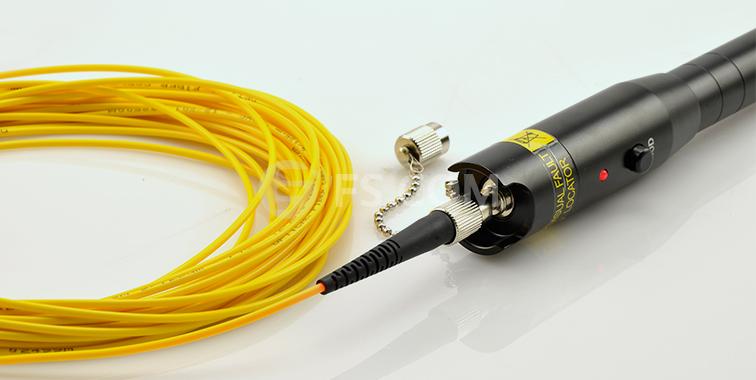
The Fibre Fault Locator (VFL) is an essential tool for every Fibre Termination Kit. It is like the continuity tester. The VFL is not one of the least expensive tools in your tool kit. It will allow you to quickly identify breaks or macrobends in the optical fibre, and identify a poor fusion splice in multimode or single-mode optical fibre.

fs-visual-fault-locator

The big difference between the VFL and the continuity tester is the light source and optical output power of the light source. The VFL typically uses a red (635-650nm) laser light source. The optical output power of the laser is typically 1mW or less. Because of the high optical output power, you should never view the output of the VFL directly.

The Visual Fault Locator is available in different shapes and sizes. Some may look like a pen. Others may be built into an optical time domain reflectometer (OTDR), and some may look like a small test equipment box. There are two types of VFLs: contact and non-contact. With a contact VFL, the optical fibre under test will make contact with the VFL. However, with a non-contact VFL the optical fibre under test will not touch the VFL.

Unlike the continuity tester, the VFL is not limited to testing multimode optical fibres 2km or less in length. The VFL can be used to verify continuity of multimode or single-mode optical fibre longer than 2km. Due to attenuation of the 635–650nm laser light source by the optical fibre, macrobends may not be detectable beyond 1km in multimode optical fibre and 500 metres in single-mode optical fibre. The same holds true for finding breaks in the optical fibre through the jacket of the fibre-optic cable.

How to Use Visual Fault Locator

As with the continuity tester, the first thing you will need to do is clean the connector endface and inspect it with a microscope. If the endface finish is acceptable, the VFL can be connected to a Optical Fibre Connectors should not be viewed directly during this testing.

The VFL fills the core of the optical fibre with light from the laser. The light from the laser escapes the optical fibre at a break or macrobend. The light escaping from the optical fibre will typically illuminate the buffer surrounding the optical fibre. Macrobends are not always visible through the jacket but are typically visible through the buffer. Breaks may be visible through the jacket of the fibre optic cable depending on jacket color, thickness, number of optical fibres in the cable, and amount of strength member.

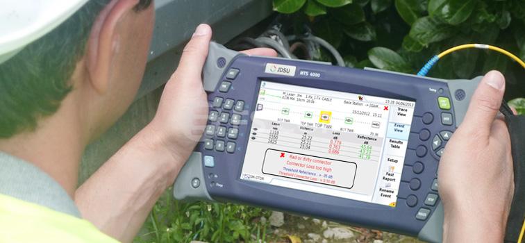
The VFL and the fibre OTDR work hand in hand with each other when it comes to locating breaks in an optical fibre. The OTDR can provide the operator with the distance the break. The VFL allows the operator to see the break in the optical fibre.

jdsu-otdr

Fibre optic cables are not the only place where the optical fibre may break. The optical fibre may break inside the connector or connector ferrule. Unless the optical fibre is broken at the endface of the connector, it is not visible with a microscope.

Usually, students connect cables that look great when viewed with the microscope but fail continuity testing. When this happens, the hardest part is determining which connector contains the break in the optical fibre. Without a VFL in the classroom, students would have to cut the cable in half and use the continuity tester to identify the bad connection.

The VFL will often identify the bad termination or connector.  Looking at the photograph, you can see VFL illuminating the break in the optical fibre. The output of the VFL is so powerful that it penetrates the ceramic ferrule.

The visual fault locator can be used to test the continuity of an optical fibre in the same manner. The first step when using the continuity tester is to clean and visually inspect the end face of the connector before inserting it into the continuity tester. After the connector has been cleaned and inspected, you need to verify that the continuity tester is operating properly. Turn the continuity tester on and verify that it is emitting light.

The visual fault locator also can be used to locate a macrobend in an optical fibre. However, macrobends do not allow nearly as much light to penetrate the buffer and jacket as does as break in the optical fibre. Locating a macrobend with the VFL may require darkening the room.

Macrobends and high loss fusion splices appear the same on an OTDR trace. The VFL allows the identification of a high-loss fusion splice.

Cable Testing With Fluke Cable Tester

No matter installing new cable, or troubleshooting the existing cable, cable testing plays an essential role in the process. Common tests for datacom cabling include length, wiremap, attenuation, NEXT, DC loop resistance, and return loss. When doing cable testing must with the Fibre Tester, and the Fluke Network Cable Tester is popular.

As networks evolve, so do the requirements of the cabling infrastructure to support them. New standards are continuously being developed to provide guidelines for cabling professionals when installing, testing, troubleshooting, and certifying either copper and fibre. Whether it’s 10BASE-T, 100BASE-TX or 1000BASE-T, there are specific requirements and potential pitfalls in implementing these technologies. And 10GBASE-T, it becomes even more critical to keep current with the latest proliferations in cabling and cable testing.

Cable testing provides a level of assurance that the installed cabling links provide the desired transmission capability to support the data communication desired by the users. Cable test instruments are designed with a variety of focused features for particular field tasks. They vary in price, performance, and application.

For example, there are typically two types of tools for checking network connectivity: the network tester tool and the Fluke tester. Sometimes an engineer will carry a noise generator which not only checks ethernet networks but also telephone lines. Network tester tool is the network checker which plugs directly into the line and reads out what line is connected on that drop, or if there is no signal there. This can also be done with a laptop computer, but it is easier to carry a network tester, since it is far smaller. The Fluke tester will read all four twisted pairs of a cable right from the drop at the workstation all the way back to the server room and will show exactly which pairs are good and if any are crossed or open. The engineer can put a noise on the line and trace it back to the complex loom of cables in the server room all arriving in the same area at the main switch or patch panel.

Verification test tools perform basic continuity functions, they assure that all wires in a cabling link are connected to the proper termination points and not to any other conductors. In twisted pair cabling, it is critical to maintain the proper pairing of the wires. Better verification test tools also verify wire pairing and detect installation defects like “split pairs”. Verification test tools may also assist in troubleshooting by providing a toner to locate a cabling link. Verification tools sometimes include additional features such as an Fibre OTDR to determine length of a cable or distance to a break or short circuit. These test tools do not provide any information on bandwidth or suitability for high-speed data communication.

FS.COM Provides A Full Line Of Fibre Adapter Panels

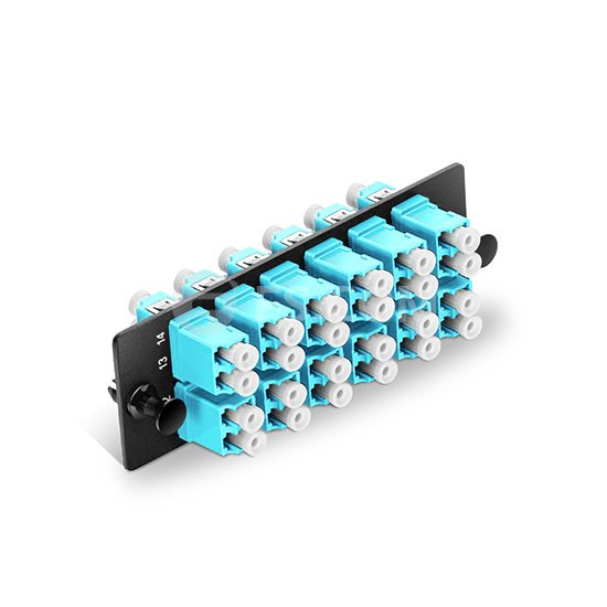
Different connector types can mean trouble for your network if you’re not prepared, and a fibre optic adapter panel(also called fibre optic adapter plate) can easily solve it. Fibr Adapteer Panels (FAP) are used for patching fibre cable to the termination enclosure like fibre wall cabinets, rack mount fibre cabinets or rack mount fibre shelf. It enables you to make quick and easy fibre patch panel connections as they can snap into the enclosures easily.

Fiber Adapter Panel

Benefits From Fibre Adapter Panels:
  • Adapter panels snap easily into all standard fibre enclosures, cabinets, and patch panels;
  • Panels with bronze sleeves are more economical and well-suited for multimode applications;
  • Panels with ceramic sleeves fit well into single mode applications;
  • High density applications can be reached through Dual and Quad LC applications.

Make sure you can handle any upgrade or new installation with a fibre optic adapter panel. Fibre adapter panels are designed to accommodate many different connections, FS fibre adapter plates accommodate a vast assortment of connectors, such as LC, SC, ST, MTP, MTRJ, unloaded, blank and so on. Whether you want to integrate 6 LC Duplex couplers, 6 MTP couplers, 12 ST Simplex couplers and many more, we have the fibre adapter plates that get the job done right. A blank metal adapter panel is also available. The adapter panels are easily snapped into the enclosures with snap lock mounting fixtures. Blank panels are available for use as dust covers.

FS.COM fibre adapter panels/plates also can come with various fibre adapters, such as LC/SC/ST/FC/MT-RJ, E-2000 fibre optic adapters, compatible with simplex or duplex and meet TIA/EIA-568-B.3 requirements. Our adapter plates include phosphor bronze or zirconia ceramic split sleeves to fit specific network requirements. LC and SC adapter housing colors follow the TIA/EIA-568-C.3 suggested color identification scheme. Multimedia modular panels allow customisation of installation for applications requiring integration of fibre optic and copper cables. Blank fibre  adapter panels reserve fibre adapter panel space for future use.

Fibre Adapter Panels Features:
  • Loaded with LC, SC, ST, MPO and unloaded blanks;
  • Simplex and duplex (6-pack or 8-pack);
  • Choose between Low and High-density panels, bronze or ceramic sleeves;
  • Ideal for 6-fibres, 8-fibres, 12-fibres or 24-fibres, 48-fibre and 72-fibres applications;
  • Plates are available for mounting Bezel style jacks creating a mixed media environment;
  • Compatiable with all ICC’s rack, wall mount fibre enclousures and fibre patch panels.

You can choose the right fibre optic adapter panel from the following factors, including fibre adapter series, number of fibre, connection type, fibre type and number of pack. Have a wide selection of fibre adapter panels at FS, also you can buy other cables management, inclding fibre optic splice closure, fibre distribution box, Optical Distribution Frame, fibre termination box, fibre optic faceplates, network faceplates, cable Ties, wire Loom, cable wire markers, Managed Cable Hook & minder, kelon article backplane and so on.

The Troubleshooting Of Fiber Optics

Fiber optics once just meet the needs of high performance systems, but now it has widely spread in various types of networks. If you are familiar with Network Cabling, then you will soon find that fiber is a kind of something completely different. Not only because of its installation process is quite different with copper wiring, and troubleshooting methods also have very big differences. Compared with copper wire, fiber optics is more fragile, so there will be some potential failures exist when use.

The Most Common Troubleshootings In Fiber Optics

Any network professionals who have done network troubleshooting are clear that this is a complex process. So know where to start looking for faults is very important. Here are some of the most common fiber failures and the possible factors cause these faults, the information will help users to predict the network faults with bases.

Fiber break is usually due to external physical extrusion or excessive bending;

Transmission power shortage;

The Optical fiber laying distance is too long may cause a loss of signal;

Connector damage may result a loss of signal;

Fiber Optic joints and connectors faults may cause a loss of signal;

The excessive use of fiber optical joints and connectors may cause a loss of signal;

Fiber patch panel or splice tra connection failure;

Generally speaking, if the connection is completely unreasonable, then it may be fiber breakage. But if the connection is intermittent, may be the following reasons:

Poor junction levels or multiple junction times cause serious optical attenuation;

The dust, scratches, fingerprints, humidity and other factors damage the connector;

The transmission power is too low;

Connector errors in the Distribution Cabinet.

Collecting Information

Collecting the fault performance and the basic information of possible causes. Using any available means, the key of troubleshooting is to get valuable information by asking the right questions.

The following are some of the problems should be first asked.

If anyone had moved the fiber (dismantling or reconnect) or moved the PC recently?

Find out whether recently PC is disconnected or be moved is very important. If the fiber optical cable is disconnected from the PC, then it is likely that the cable simply has not been properly connected, or problems occur when reconnection, or the fiber may damage when disconnect.

Whether the device recently was moved?

Most copper network failures are caused by someone walking too fast to the original sticking wall table, or cleaners accidentally move the table to do vacuum cleaning. Moving the table without unplug the network cable, the cable is likely to be excessive dragged, or is held down by table or folded. If such action would damage to a copper wire, then you can imagine what consequences will be brought to the fiber, as it is made ​​of glass.

The vast majority of users are not clear that Fiber Optics Cable will break in the situation of stepped on or bend too much.

The Confusing Concept Of Optical Modem And Media Converter

About Fibre Optic Modem

Optical Modem, also known single-port optic multiplexer, is a point-to-point type terminal equipment which uses a pair of optic fibres to achieve the transmission of E1 or V.35 or 10base-T. Fibre modem has the function of modulation and demodulation. Optical modem is a local network relay transmission equipment, suitable for base station transmission fibre terminal equipment and leased-line equipment.

Fibre modem is similar to the baseband MODEM (digital modem). The only difference from baseband MODEM is that it access fibre line, the optical signal. The multi-ports optic transceiver generally called multiplexer. For multi-port Fibre Optic Multiplexer is normally be directly called “multiplexer”, single-port multiplexer is generally used on the client, similar to commonly used WAN line (circuit) networking with the baseband MODEM, and also named for “fibre modem”, “optical modem”.

About Fibre Media Converter

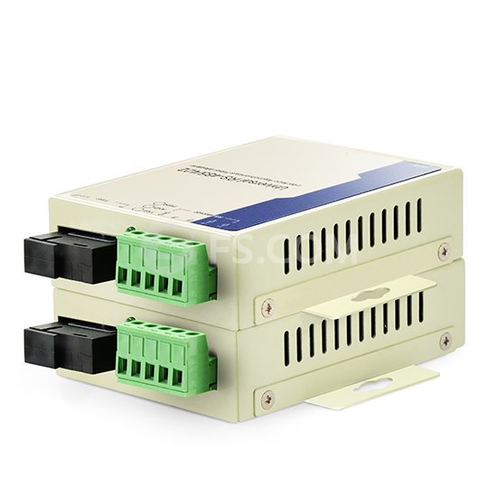
Fibre Media Converter is a simple networking device making the connection between two dissimilar media types become possible. Media converter types range from small standalone devices and PC card converters to high port-density chassis systems that offer many advanced features for network management.

converter

Fibre media converters can connect different local area network (LAN) media, modifying duplex and speed settings. Switching media converters can connect legacy 10BASE-T network segments to more recent 100BASE-TX or 100BASE-FX Fast Ethernet infrastructure. For example, existing half-duplex hubs can be connected to 100BASE-TX Fast Ethernet network segments over 100BASE-FX fibre.

When expanding the reach of the LAN to span multiple locations, media converters are useful in connecting multiple LANs to form one large campus area network that spans over a limited geographic area. As premises networks are primarily copper-based, media converters can extend the reach of the LAN over single-mode fibre up to 160 kilometres with 1550 nm optics.

Wavelength-division multiplexing (WDM) technology in the LAN is especially beneficial in situations where fibre is in limited supply or expensive to provision. As well as conventional dual strand fibre converters, with separate receive and transmit ports, there are also single strand fibre converters, which can extend full-duplex data transmission up to 120 kilometres over one optical fibre.

Other benefits of media conversion include providing a gradual migration path from copper to fibre. Fibre econnections can reduce electromagnetic interference. Also fibre media converters pose as a cheap solution for those who want to buy switches for use with fibre but do not have the funds to afford them, they can buy ordinary switches and use fibre media converters to use with their fibre network.

The Difference Between Media Converter And Optical Modem

The difference between the media converter and optical modem is that the media converter is to convert the optical signal in the LAN, simply a signal conversion, no interface protocol conversion. While, fibre modem for WAN is the optical signal conversion and interface protocol conversion, protocol converter has two types of E1 to V.35 and E1 to Ethernet.

In fact, as the developing of network technology, the concept of media converter and fibre modem has become increasingly blurred, which are basically can be unified for the same equipment. Media converter becomes the scientific name of fibre modem.